Making a clock with a common microcontroller like an Arduino isn’t very difficult. However, if you’ve tried it, you probably discovered that keeping track of wall time is difficult without some external hardware. [Barzok] has a very minimal clock build. It takes a handful of LED arrays with an integrated driver, an Arduino Nano, a real-time clock module, and a voltage regulator.
We can gather that [Stefan] is a professional machinist by trade. Like all professionals who do the same thing for work and play, he was spoiled by the nicer tools at work. One tool in particular, a toolmaker’s magnet, always came in handy. These are strong magnets that have been ground flat, square, and parallel.
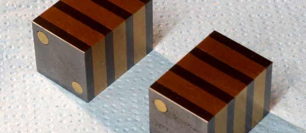
He really only needed one magnet, so he started to build a 20 x 20 x 100 mm one. It would be made out of alternating mild steel and brass plates. The steel plates would have a hole drilled through them and he’d place a correctly oriented magnet in the middle. It would all be clamped and glued together.
The build was going pretty well when he decided that he couldn’t really trust the glue alone. He had just begun grinding, but decided to switch to a quick drilling operation. Two brass rods through the whole assembly would be enough to hold it together. He started drilling, and then, suddenly, he had two magnets.
The assembly had broken in half. He decided that, all things considered, two 20 x 20 x 50 mm magnets were also handy. So he completed the drilling, and ground the new set of magnets to be a perfect match to each other. In the end he had a tool that looks just as expensive as the commercial option. There is also a video series on the magnets, part 1 and part 2, viewable after the break.
If you come from somewhere with a tradition of eating a meal of roast turkey or goose to celebrate Christmas, Thanksgiving, or other holidays, then maybe you’ve encountered the three-bird roast, or Turducken. A deboned duck is stuffed with a deboned chicken, and in turn the combination is stuffed into a turkey All the gaps are filled with sausage meat stuffing, and the resulting combination is roasted for a serious meat-fest. Vegetarians, please look away.
It’s something of an excess of poultry, but the three-bird roast is a delicacy that definitely works. We’re not so sure about the link that prompted this journey into celebration poultry dishes by reminding us of a turducken, but we’ll leave the verdict to you the reader. Someone has created an unholy turducken-style chain of emulators that delivers a Sinclair ZX Spectrum on a Linux machine via Windows, DOS, and the Commodore 64. If it had its own word like the poultry dish it might be a Linwindoscomtrum, but let’s not go there.
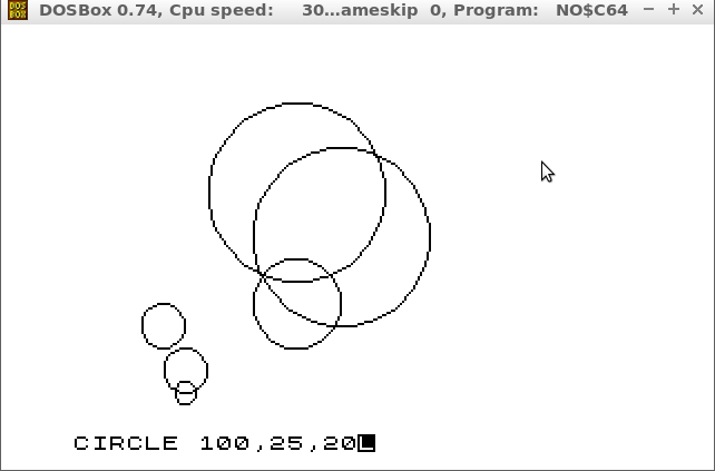
The linwindoscomtrum in all its glory.
So how have they done it? First, they took Lubuntu, and installed WINE. (OK, Wine Is Not an Emulator, we know that, but go with the story for a moment) Then they installed DOSBox under WINE for a DOS command prompt, and ran no$C64, a Commodore 64 emulator. On that they ran the c642spec Sinclair ZX Spectrum emulator, and finally arrived in a ZX BASIC prompt.
The author does make the point at the start of the write-up that it’s a waste of ten minutes, but even though the result is an overly complex way to slowly emulate an archaic home computer on a modern one we’ll still give them ten out of ten for the effort.
Incidentally, the author does not identify themself and there is little clue in the form of the rest of the site to identify them, so unusually for a Hackaday piece we can not give credit where it is due. We do however salute the anonymous emulator pilot for their glorious folly.
If you look around the street furniture of your city, you may notice some ingenious attempts to disguise cell towers. There are fake trees, lamp posts with bulges, and plenty you won’t even be aware of concealed within commercial signage. The same people who are often the first to complain when they have no signal it seems do not want to be reminded how that signal reaches them. On a more sinister note, government agencies have been known to make use of fake cell towers of a different kind, those which impersonate legitimate towers in order to track and intercept communications.
In investigating the phenomenon of fake cells, [Julian Oliver] has brought together both strands by creating a fake cell tower hidden within an innocuous office printer. It catches the phones it finds within its range, and sends them a series of text messages that appear to be from someone the phone’s owner might know. It then prints out a transcript of the resulting text conversation along with all the identifying information it can harvest from the phone. As a prank it also periodically calls phones connected to it and plays them the Stevie Wonder classic I Just Called To Say I Love You.
In hardware terms the printer has been fitted with a Raspberry Pi 3, a BladeRF software-defined transceiver, and a pair of omnidirectional antennas which are concealed behind the toner cartridge hatch. Software comes via YateBTS, and [Julian] provides a significant amount of information about its configuration as well as a set of compiled binaries.
In one sense this project is a fun prank, yet on the other hand it demonstrates how accessible the technology now is to impersonate a cell tower and hijack passing phones. We’re afraid to speculate though as to the length of custodial sentence you might receive were you to be caught using one as a private individual.
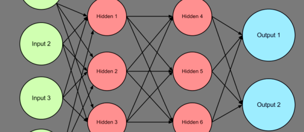
When you want a person to do something, you train them. When you want a computer to do something, you program it. However, there are ways to make computers learn, at least in some situations. One technique that makes this possible is the perceptron learning algorithm. A perceptron is a computer simulation of a nerve, and there are various ways to change the perceptron’s behavior based on either example data or a method to determine how good (or bad) some outcome is.
What’s a Perceptron?
I’m no biologist, but apparently a neuron has a bunch of inputs and if the level of those inputs gets to a certain level, the neuron “fires” which means it stimulates the input of another neuron further down the line. Not all inputs are created equally: in the mathematical model of them, they have different weighting. Input A might be on a hair trigger, while it might take inputs B and C on together to wake up the neuron in question. Continue reading “Machine Learning: Foundations”→
Most inexpensive 3D printers use a type of lead screw to move some part of the printer in the vertical direction. A motor turns a threaded rod and that causes a nut to go up or down. The printer part rides on the nut. This works well, but it is slower than other drive mechanisms (which is why you don’t often see them on the horizontal parts of a printer). Some cheap printers use common threaded rod, which is convenient, but prone to bad behavior since the rods are not always straight, the threads are subject to backlash, and the tolerances are not always the best.
More sophisticated printers use ACME threaded rod or trapezoidal threaded rods. These are made for this type of service and have thread designs that minimize things like backlash. They typically are made to more exacting standards, too. Making the nut softer than the rod (for example, brass or Delrin) is another common optimization.
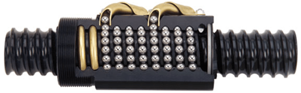
However, when lead screws aren’t good enough, mechanical designers turn to ball screws. In principle, these are very similar to lead screws but instead of a nut, there is a race containing ball bearings that moves up and down the screw. The ball bearings lead to less friction.
Misumi recently posted a few blog articles about ball screws. Some of the information is basic, but it also covers preloading and friction. Plus they are promising future articles to expand on the topic. If you prefer to watch a video, you might enjoy the one below.
We know what it’s like to wait for newly released electronic parts. Clicking refresh every day at your favorite online retailers, reading reviews published by the press who got preview units, and maybe even daring to order implausibly cheap devices from foreign lands. The ESP32 has many of us playing the waiting game, and we’ll level with you — they’re out of stock most places. But, if you look hard enough you can find one. At least, you could find them before we wrote this quick roundup of ESP32 hardware. If hearing about parts that are just out of reach is your sort of thing, then read on, you masochist!