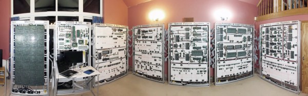
The HTC Vive is the clear winner of the oncoming VR war, and is ready to enter the hallowed halls of beloved consumer electronics behind the Apple Watch, Smart Home devices, the 3Com Audrey, and Microsoft’s MSN TV. This means there’s going to be a lot of Vives on the secondhand market very soon, opening the doors to some interesting repurposing of some very cool hardware.
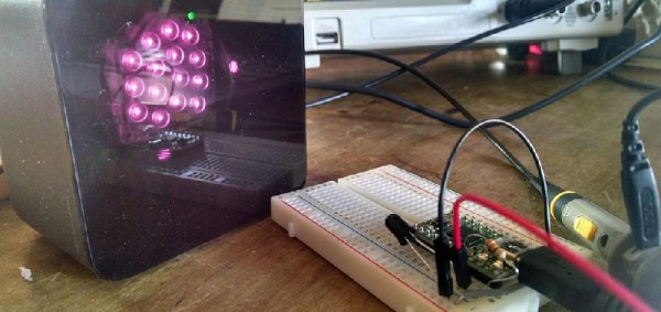
[Trammell Hudson] has been messing around with the Vive’s Lighthouse – the IR emitting cube that gives the Vive its sense of direction. There’s nothing really special about this simple box, and it can indeed be used to give any microcontroller project an orientation sensor.
The Vive’s Lighthouse is an exceptionally cool piece of tech that uses multiple scanning IR laser diodes and a bank of LEDs that allows the Vive to sense its own orientation. It does this by alternately blinking and scanning lasers from left to right and top to bottom. The relevant measurements that can be determined from two Lighthouses are the horizontal angle from the first lighthouse, the vertical angle from the first lighthouse, and the horizontal angle from the second lighthouse. That’s all you need to orient the Vive in 3D space.
To get a simple microcontroller to do the same trick, [Trammell] is using a fast phototransistor with a 120° field of view. This setup only works out to about a meter away from the Lighthouses, but that’s enough for testing.
[Trammell] is working on a Lighthouse library for the Arduino and ESP8266, and so far, everything works. He’s able to get the angle of a breadboard to a Lighthouse with just a little bit of code. This is a great enabling build that is going to allow a lot of people to build some very cool stuff, and we can’t wait to see what happens next.
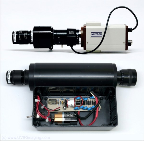

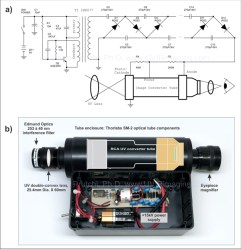 If you’re thinking UV is a broad brush, you’re right. [David Prutchi] says he is most interested in Solar Blind UV (SBUV):
![The 3D scan of a small cave near Louisville (source: [caver.adam's] Sketchfab repository)](https://hackaday.com/wp-content/uploads/2016/06/bildschirmfoto-2016-06-27-um-20-02-11.png)


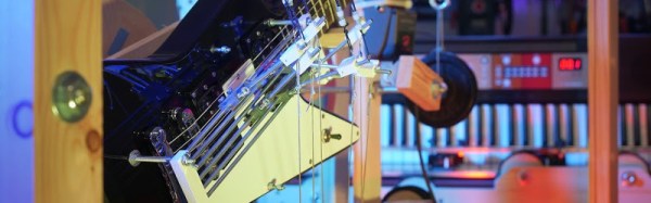
 [Niklas Roy] however has a different vision when it comes to mechanical music. He’s created