Ding, dong; the office is dead. The real office is in your head.
This is what I tell myself when working from home gets too weird, too stale, too impossible. By now, many of you know some version what I’m talking about. Our circumstances may vary wildly, but the outcome is the same: working from home is pretty awesome, but, some small, secret part of us longs for the office. Why is that?
The answer will be different for everyone. Maybe you’re a social butterfly who misses face-time and the din of familiar voices. Maybe you just appreciate the physical separation between work and home life. If you’re lucky, the choice to go to the office is yours at this point, and if not, well, we have to wonder if you’re looking for new work. It’s 2022, we’re still in a pandemic, and of course there’s this, that, and the other multi-national Dumpster fire you haven’t heard about yet. Isn’t it time we prioritized work output over office attendance when it comes to our livelihoods?
Dovetail joints on a piece of furniture are one of those features that make it say “master carpenter” rather than “IKEA”. Traditional hand-made dovetails require accurate measurements and even more accurate sawing and chiseling, skills that may take years to develop. A slightly less artisanal method is to use a router and a dovetail template; the router makes perfectly straight cuts while the template makes sure it goes only where it needs to go.
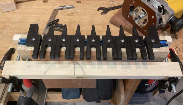
If you haven’t got one of those templates yet, check out [Guy Perez]’s design for an adjustable dovetail template that’s easy to produce with a 3D printer. It consists of ten separate pieces mounted on a T-rail, which enables them to slide sideways and thereby generate pins and tails of varying widths. The T-rail is mounted on a wooden body with an integrated clamp to hold the target piece, as well as an endstop to provide a reference for all measurements.
As you can see in the video embedded below, the resulting jig is easy to use and should result in near-perfect dovetails each time. [Guy] made the CAD files available as well as detailed instructions on their design, so you can easily adjust them if you need pieces with a different tail angle or want to use thicker wood.
While this jig will make cutting ordinary dovetail joints a lot easier, you can still show off your manual skills by making an impossible mallet. Want to join metal bits instead? Check out this cute little dovetail cube.
I hope last week’s introduction to bulk material handling got you all thinking up amazing hacks, and we’ll soon be reporting on DIY Cap’n Crunch Robots galore. This week we’ll look at how to measure particle sizes, separate particles, and even grind them up when you need to.
Measuring Material Properties
Last week we talked about cohesive strength. Bulk material behaves somewhere between a solid and a liquid — if you’ve done your homework, it flows down the funnel just fine. But if you haven’t, it sticks together and holds up the rest of the material. Cohesive strength is the measure of how much weight the material at the bottom of the funnel can hold up.
You can get a rough measurement by packing material in a box with a square hole at the bottom. One side of the hole should have a retractable slide. Slowly withdraw the slide, making the hole rectangular. Material will bridge over, and then at some point a larger chunk will fall out. This is about the size of the minimum opening that will not arch, and a practical measure of the material’s cohesive strength.
Many materials cohere better when wet. Dry a sample in a microwave to determine the percent moisture by weighing it before and after.
Cohesive strength is closely allied to shear strength. If you want to measure shear strength, cut two 1 cm wide rings of 5 cm diameter PVC pipe, stack them, pack with material, put a disk atop the material and load it, then drag the top ring off the bottom with a spring scale. The force per unit area is the shear strength at that pressure. If it starts packing you’ll see it in the curve.
Packing factor is another useful measurement. Gently shake material to fill a rigid container and weigh it. Now empty the container and refill, packing the material as hard as you can with a length of 1” dowel. Reweigh, and the ratio of the two weights tells you how well the material packs.
Real bulk material is almost always made up of particles of varying sizes, shapes, and compositions. Dirt is particles of different kinds of mineral and organic matter varying from outright rocks to sub micron clay particles. If you’re having problems, getting a graph of material size distribution can be helpful.
For particles above about 75 μM, you can measure the sizes with sieves. If you want to be fancy, they sell nice sets of metal sieves with wire mesh in the bottom. Screen assortments are cheaper. Below 75 μM, you have to use a hydrometer. This is messy and takes a while, but does work.
The idea is to mix the material with soapy water and then use a hydrometer from the auto parts store to measure the density. The particles fall out by Stokes law, big ones first. Stokes law is just that the drag force on a sphere is proportional to the square of the radius. Mass will go up as cube of the radius, so large particles fall faster than small ones. As they fall out, the density of the fluid decreases. This page describes how to do it, and this page has a handy calculator for interpreting the results.
Grinding
You can also change the size of particles in your mix. If particles are too large, they can be crushed or ground. You can separate by size and only grind some of the sizes or discard some of the material. There’s a whole science to grinding. The finer you grind, the harder it gets to grind. Cosmetics and pharmaceutical companies are full of grinding experts.
In general, there are three ways to make something smaller – crush it, cut it, or hit it.
Crushing is straightforward. Use rollers or jaws, a rolling pin or a rock crusher. Don’t overlook the vise. A jaw crusher only crushes particles larger than the jaw space, useful to make a certain size. Rock crushers have a complex motion (video) that should nonetheless be easily imitated by a hacker project. Amateur/hobby gold prospectors have an accessible community.
Crushing action in rollers only works until the particle is small enough that the surface of the roller deforms instead of the particle. Stones have been used to crush grain into flour for most of history.
Cutting is best for soft things, like gummy worms, and tough things (video.). Make sure the cut material has an easy path out. Think of an old fashioned kitchen meat grinder. .
If you want small particles, you need an impact grinder. A coffee mill or blender works by striking the particle with a fast moving impactor. This can be a blade – useful if the material first needs to be cut up, as in a coffee mill – or blunt. Many industrial mills use two pivoting weights on a shaft, and this unit just uses chains (video).
Another impact mill is the ball mill. Rotate a drum on it’s side with steel balls and the material. The balls travel up the side, then fall back down, striking the material.
All these work by fracturing the material. What if you’re trying to powder something that doesn’t fracture, say rubber O rings? For that, there’s cryogenic grinding.
Many rubbery materials are really glasses — materials that are a gloppy liquid at a higher temperature, often brittle at a cool temperature, and soft in-between. The glass you’re probably thinking of is a brittle, breakable material at room temperature, but at high temperature is a liquid. The transition point is the ‘glass transition temperature’.
So what about our O rings? If they’re natural rubber their transition point is about -70° C. Below that temperature they’re brittle and can be ground up. Unfortunately, grinding is going to put heat back in. So consider grinding slowly – some labs grind biological materials like skin samples with a special mortar and pestle cooled beforehand with liquid nitrogen. Just be sure everything in contact with the material has been cooled, and use a thick walled container with lots of thermal mass.
Separating Wheat From Chaff
Sometimes you have a mix and need to separate it. Your roommate dumped all the gummy bears and all those weird ginger candies into a bowl or whatever. Last week we introduced particle segregation as a bad thing. But when you want to un-mix a mixture, it can be a good thing. Any of the techniques from last week can be an aid.
Sieves and screens work to separate by size. They clog unless the material keeps moving over them. One simple way to do this is to flow the material over sieves on a slanted board, finest sieve first. Another is to mechanically shake the screen. Paper filters are just fine screens, and do clog.
A trommel is a slowly turning cylinder with walls of different sized screens along it’s length. Material is fed into the fine screen end and slowly moves towards the other.
Stokes law provides another way to separate materials as we saw above. Make an upward air draft in a vertical pipe. Deliver the material into the pipe part way up. Materials with more drag than weight will go up, larger materials will go down. You can use the air speed to control the size of particle. An industrial machine called an air classifier does this with higher velocity air blowing material into the rim of a spinning set of blades.
It could be the air (or another gas) you want to remove. There are a couple ways to do it. The first is the cyclone familiar to wood shops. The second is even simpler – inject the air/material mix into the top of a tall, slender container with a tube that extends about halfway into the container. Let the air out from an outlet pipe in the roof. The air flow expands, slows down, and the material falls out.
You can just blow the material sideways – the age old system of threshing wheat works this way. Wheat comes from the plant with a husk, you beat it with a flail to loosen the husk, giving you wheat grains and chaff mixed. Put the mix on a blanket and have four peasants toss it repeatedly. The chaff blows away in the wind.
Inertial Separation
A very sensitive separation technique is inertial separation. Here’s a mix of gummy colas and jelly beans. We separated them by tilting and gently shaking the sheet. A material moves on a sheet by staying in place until the acceleration is more than some critical value. Then it rolls or slides.
If your material is dirt or such, run a magnet through it. There’s iron ore and bits of human generated iron in a lot of soil. It can get into motors and such. If you need it out run the material past magnets. An eddy current separator uses AC magnetic effects to do the same with nonferrous metals.
You can also segregate materials by dissolving them. A mixture of table salt and white sand would seem impossible, but if you stir it into water, then decant and boil off the water, the salt and sand can be recovered separately. But we think we’re veering into chemistry now, and we should stop.
Next time we’ll finish up by looking at controlling movement: building gates and contraptions that move your bulk material without clogging up.
I’ll confess. Although printf-style debugging has a bad rep, I find myself turning to it on occasion. Sure, printf is expensive and brings in a lot of code, but if you have the space and time to use it while debugging you can always remove it before you are finished. However, what if you don’t have an output device or you are using it for something else? If you are using most modern ARM chips, you have another option — a dedicated output channel that is used for several things, including debugging output. I decided I wanted to try that on the Blackpill running mbed, and found out it isn’t as easy as you might think. But it is possible, and when you are done reading, you’ll be able to do it, too.
I’m writing this using the STM32-specific ST-LINK hardware. If you use other JTAG devices like the BlackMagic probe, you probably already have this set up for you.
What You Get
I’ll start backward with the end result, then talk about the software, so you’ll be good and motivated by the time you get to the hardware requirements. Spoiler alert: your existing hardware might need a quick hack to make it work, although you can buy something off the shelf if you prefer.
Here is a very simple test program:
SWO_Channel debugport;  // requires #include "SWO.h"
int main()
  {
  unsigned count=0;
  debugport.printf("\r\nHello World from SWO\r\n");
  debugport.printf("CPU SystemCoreClock is %d Hz\r\n", SystemCoreClock);

  while (1)
    {
    led = !led; // flip LED if output is true
    ThisThread::sleep_for(rate); // sleepy time
    if (count % 10) debugport.putc('*'); else debugport.printf("%d\r\n",count);
    count++;
    }
}
Some Samsung TVs come with a system called One Connect, where all external cabling is connected to a separate box so that only one small signal cable goes to the TV. In some versions, the cable linking the TV with its Connect Box is a pure fiber optic cable that’s nearly transparent and therefore easy to hide.
Thin fiber optic cables are fragile however; when [Elecami Wolf] got one of these TVs for a very low price it turned out that this was because its One Connect cable had snapped. Replacement cables are quite expensive, so [Elecami Wolf] went on to investigate the inner workings of the fiber optic cable and figured out how to repair a broken one.
The cable consists of four pairs of plastic-coated glass fibers, which are attached to receivers and transmitters inside the thick connectors on either end. Repairing the cable required two things: figuring out which fibers should connect to each other, and a reliable way of connecting them together.
The first was difficult enough: a simple 1:1 connection didn’t work, so it took a bit of work to figure out the correct connection setup. One clever trick was pointing a camera at a working cable and comparing the flashing lights at each end; this helped to identify the right order for two of the four pairs. For the other two, a combination of reverse-engineering the electronic circuits and some systematic trial-and-error yielded a complete wiring diagram.
For the second part, [Elecami Wolf] called on a fiber optic expert who lent him a fusion splicer. This is a rather neat piece of equipment that semi-automatically brings two pieces of fiber together and welds them with an electric arc. Once this was complete, it was a matter of covering the splices to protect them from sharp bends, and the fancy TV was working again.
Although not everyone will have access to a multi-mode fusion splicer machine, [Elecami Wolf]’s videos provide fascinating insights into the workings of modern fiber-optic based consumer electronics. This might be the first fiber-optic splicing attempt we’ve seen; but if you’re trying to hook up an optical fiber to your circuit, this ball lens setup is a neat trick.
When Portal came out in 2007, developers Valve chose not to release the groundbreaking title on an obsolete Nintendo console long out of production. Nobody cared at the time, of course, but [James Lambert] is here to right that wrong. Yes, he’s porting Portal to the N64.
The port, or “demake,” as [James] calls it, has been under construction for some time. The project has posed some challenges: Portal was developed for PCs that were vastly more powerful than the Nintendo 64 of 1996. Thus, initial concerns were that the console wouldn’t be able to handle the physics of the game or render the recursive portal graphics.
However, hard work has paid off. [James] has chipped away, bit by bit, making improvements to his engine all the while. The latest work has the portals rendering nicely, and the companion cube works just the way you’d expect. There’s also a visible portal gun, and the engine can even render 15 recursive layers when looking through mirrored portals. Sixteen was too much.
Of course, there’s still lots to do. There’s no player model yet, and basic animations and sound are lacking. However, the core concept is there, and watching [James] flit through the not-quite-round portals is an absolute delight. Even better, it runs smoothly even on original Nintendo hardware. It’s a feat worthy of commendation.
We had no idea what [James] had in store back when we featured his work creating real-time shadows on N64 hardware. Now we know! Video after the break.
As one of the most popular buses today for on- and inter-board communication within systems, there’s a good chance you’ll end up using it with an embedded system. I2C offers a variety of speeds while requiring only two wires (clock and data), which makes it significantly easier to handle than alternatives, such as SPI. Within the STM32 family of MCUs, you will find at least one I2C peripheral on each device.
As a shared, half-duplex medium, I2C uses a rather straightforward call-and-response design, where one device controls the clock, and other devices simply wait and listen until their fixed address is sent on the I2C bus. While configuring an STM32 I2C peripheral entails a few steps, it is quite painless to use afterwards, as we will see in this article. Continue reading “Bare-Metal STM32: Using The I2C Bus In Master-Transceiver Mode”→