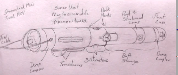
[Doug] and [Kay] have been building a steel 70-foot sailboat for the last few years, and since it’s a little too cold to work outside their home/shop in Oklahoma, they’re bringing their projects inside for the winter. Until it warms up a bit, they’re working on an underwater ROV capable of diving to 3000 feet below the waves, maneuvering on the ocean floor, and sending video and side-scan sonar back to their homebuilt ship.
Like [Doug] and [Kay]’s adventures in shipbuilding, they’re documenting the entire build process of ROV construction via YouTube videos. The first video covers the construction of a pressure vessel out of a huge piece of 10″ ID, half inch wall steel pipe. The design of the ROV will look somewhat like a torpedo, towed by the ship with cameras pointing in all directions.
For communication with the surface everything is passing over a single Cat5 cable. They’re using an Ethernet extender that uses a twisted wire pair to bring Ethernet to the ocean bottom. With that, a few IP webcams relay video up to the ship and a simple Arduino setup allows for control of the ships thrusters.
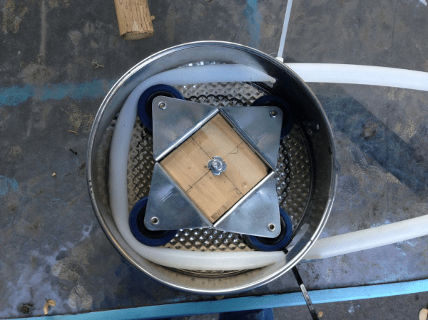
The thrusters? Instead of an expensive custom solution they’re using off the shelf brushless motors for RC cars and planes. By potting the coils of a brushless outrunner motor, [Doug] and [Kay] found this solution makes an awful lot of sense; it’s cheap, fairly reliable, doesn’t require a whole lot of engineering, and most importantly cheap.
Bunch of videos below, or just check out [Doug] and [Kay]’s progress on their slightly out-of-date blog.
 In the wake of Google’s purchase of connected devices interest Nest, the gents at [Spark]