Pranking A Hackerspace IRC For April Fool’s Day

face

Like most hackerspaces, when the folks at DIYode, the Guelph, Ontario hackerspace, aren’t in the workshop, they’re on IRC. It’s a great way to build a community, complete with a bot that collects and catalogues to-do items, meeting topics, posts events to IRC, and even does a bit of text-to-speech so members currently at the DIYode can listen in on the IRC room. There’s also a webcam for the DIYode space that members check constantly. [Simon] thought it would be a great prank to freak out those members that constantly check the webcam, and we’ll say he succeeded with a little help from the Alabama Face Guy.

The build listens for a specific phrase in the IRC room – “Hey, someone just entered the shop without the doorbot noticing” – and sends a command via Python to an Arduino to raise and lower a cardboard cutout of a sneering face in front of the web cam. For an April Fool’s build, this is probably one of the most creative and creepy we’ve seen this year.

MP3/USB/Aux Hack Hidden Behind Cassette Facade

mp3-hiding-in-plain-sight

[Ivan] made something special with this car stereo hack. He altered the head unit to play MP3 files from USB and added an auxiliary line-in. But looking at it you’d never know. That’s thanks to the work he did to create a false button hiding the audio jack, and a false cassette hiding the USB port and MP3 player display. Possibly the best part is that the radio itself still works like it always did.

There are several components that went into making the system work. It starts with the cassette/radio head unit. To that he added an MP3 player with remote which he picked up on Deal Extreme. He wasn’t a huge fan of the IR remote that came with it so he rolled in a remote that mounts on the steering wheel. To pull everything together he used a PIC 16F877a. The microcontroller controls the lines which tell the head unit if a tape has been inserted. When [Ivan] selects either the Aux input or wants to play MP3s from a thumb drive the uC forces the head unit into cassette mode and the audio from the player is injected into the cassette player connections.

To help deter theft [Ivan] created two false fronts. The end of a cassette tape plugs into the USB port. The rewind button plugs into the Aux jack. You can get a good look at both in the demo after the break.

Continue reading “MP3/USB/Aux Hack Hidden Behind Cassette Facade”

Retrotechtacular: The Fourier Series

Here’s a really quick video which takes a different approach to understanding the Fourier Series than we’re used to. If you’re a regular reader we’re sure you’ve heard of the Fourier Series (often discussed as FFT or Fast Fourier Transform), but there’s a good chance you know little about it. The series allows you to break down complex signals (think audio waves) into combinations of simple sine or cosine equations which can be handled by a microcontroller.

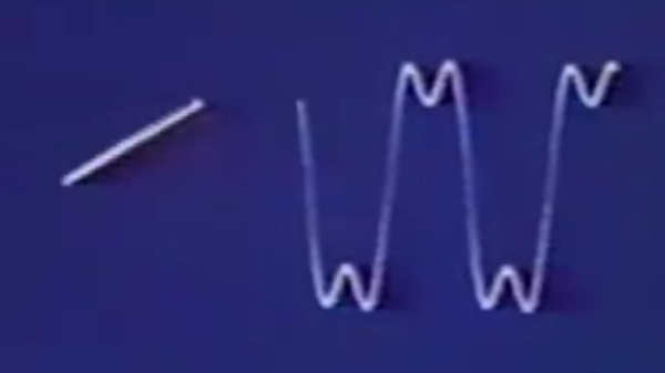
We’ve had that base level of understanding for a long time. But when you start to dig deeper we find that it becomes a math exercise that isn’t all that intuitive. The video clip embedded after the break changes that. It starts off by showing a rotating vector. Mapping the tip of that vector horizontally will draw the waveform. The Fourier Series is then leveraged, adding spinning vectors for the harmonics to the tip of the last vector. The result of summing these harmonics produces the sine-based square wave approximation seen above.

That’s a mouthful, and we’re sure you’ll agree that the video demo is much easier to understand. But the three minute clip just scratches the surface. If you’re determined to master the Fourier Series give this mammoth Stanford lecture series on the topic a try.

Continue reading “Retrotechtacular: The Fourier Series”

Adding An Optical Mouse Sensor To An Autonomous Vehicle

[Tim] is getting his drone ready for SparkFun’s 2013 Autonomous Vehicle Competition on June 8th. He has a pretty good start, but was having some problems accurately measuring travel distance. The technique he chose for the task was to glue magnets onto the axles of the vehicle and monitor them with a hall effect sensor. Those sensors are finicky and a few problems during testing prompted him to look at a redundant system. Right now he’s experimenting with adding an optical mouse sensor to the autonomous vehicle.

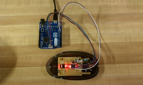
Recently we saw the same concept used, but it was meant for tracking movement of a full-sized automobile. If it can work in that application it should be perfect here since the vehicle is much closer to the ground and will be used in ideal conditions (flat pavement with clear weather). [Tim] cracked open an old HP mouse he had lying around. Inside he found an Avago ADNS-5020 sensor. After grabbing the datasheet he discovered that it’s simply an I2C device. Above you can see the Arduino Leonardo he used for the first tests.

[Tim] coded functions to monitor the chip, including some interesting ones like measuring how in-focus the surface below the sensor is. This brings up a question, is there limit on how fast the vehicle can travel before the sensor fails to report back accurately?

Hall Effect Limit Switches For A 3D Printer

hall-effect-limit-switches

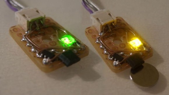
We’re used to thinking of limit switches as a mechanical device that cuts the motor connection before physical damage can occur. [Anthony] decided to try a different route with this project. He built this set of no-contact limit switches using a hall effect sensor. The small black package sticking out past the end of the protoboard is the sensor. It is used to detect a magnetic field.

[Anthony] chose to use an Allegro A3144 sensor. Apparently it is no longer in production but was easy to find for a song and dance on eBay. When thinking about the design he decided to add two LED indicators, one lights when the switch is open and the other when it has been tripped. This would have been easy to do with just one LED, but he needed to add more parts to get both working. In the lower left corner of the protoboard you can see the configurable gate device (74LVC1G58) he added to monitor the hall effect sensor and switch the output and LEDs accordingly.

Microscope Ring Light With A Number Of Different Features

microscope-ring-light

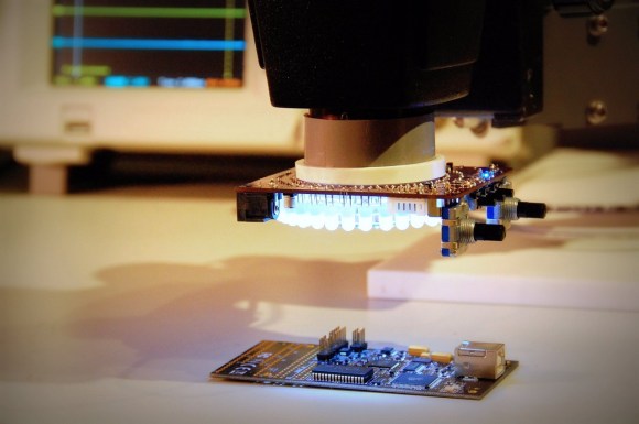
Microscopes magnify light. It makes sense that having more light reflecting off of the subject will result in a better magnified image. And so we come to Aziz! Light! It’s [Steve’s] LED light ring for a stereo microscope. It’s also a shout out to one of our favorite Sci-Fi movies.

He’s not messing around with this microscope. We’ve already seen his custom stand and camera add-on. This is no exception. The device uses a fab-house PCB which he designed. It boasts a dual-ring of white LEDs. But the controls don’t simply stop with on and off. He’s included two rotary encoders, three momentary push switches, and three LEDs as a user interface. This is all shown off in his demo video after the break.

An ATtiny1634 is responsible for controlling the device. When turned on it gently ramps the light up to medium brightness. This can be adjusted with one of the rotary encoders. If there are shadows or other issues one of the push buttons can be used to change the mode, allowing a rotary encoder to select different lighting patterns to remedy the situation. There are even different setting for driving the inner and outer rings of LEDs.

We haven’t worked with any high-end optical microscopy. Are these features something that is available on commercial hardware, or is [Steve] forging new ground here?

Continue reading “Microscope Ring Light With A Number Of Different Features”

Building A Theremincello

building-a-theremin-cello

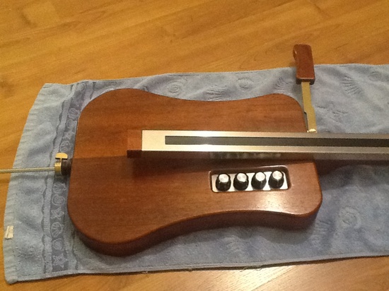
We totally missed the ball on this project. It should have been run on April Fools’ day and you would have no idea if it were real or a hoax. That’s because the very serious performance given after the break is hard to watch without a least a bit of a chuckle. The instrument shown above is a Theremincello. It’s an instrument in the shape of a cello which functions in a similar way to a Theremin.

The instrument being played in that video clip is the first generation and the one pictured above is its successor. The creator wanted to refine the electronics so that the resulting sound wasn’t so ‘flutey’. The result can be heard on the video embedded in this Theremin World article and we think they’ve accomplished the goal; it sounds much better! In the clip [Thierry Frenkel] demonstrates changing notes on the fingerboard with the left hand. The right hand which would normally bow the strings operates the lever to adjust the volume of the note being played back.

If a single fingerboard isn’t enough for your needs you may consider building this four-track design instead.

Continue reading “Building A Theremincello”