Edge Lit Plastic Bike

Edge-Lit Clear Plastic Bike Combines Nighttime Riding Safety With Aurora Borealis Flair

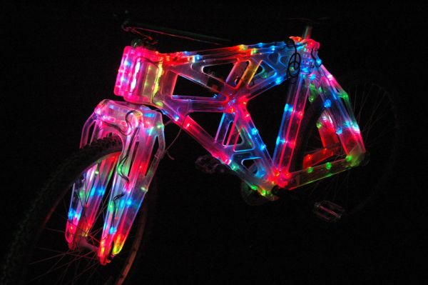
Several years ago [dan] saw some plastic frame bikes designed by MIT students. Ever since he saw those bikes he thought it would be cool to make an edge-lit plastic framed bike.

The frame is made from 1/8″ and 3/8″ thick polycarbonate sheet. The parts were designed with tongue and grooves so they fit together nicely. The joints were glued to hold everything together. Holes were drilled in the edge of the plastic large enough to fit an LED. Once the LED was inserted in the hole, it was wired up and secured with hot glue. There are about 200 LEDs on the bike, powered by a constant current LED driver circuit that [dan] designed specifically for this project.

The build process was certainly not flawless. For example, the plastic holding the bottom bracket (where the crank and pedals attach) broke. This can be avoided by increasing the amount of material in that area prior to cutting out the pieces. [dan] was able to fiberglass his broken parts back together.

[dan] admits that the bike is heavy and a little wobbly, but is definitely ride-able. He did us a favor and made all his CAD files available to anyone that wants to make one themselves. If polycarbonate is too expensive for your blood, check out this bike make from cardboard.

Fold-out Laser Cutter Prototype Promises Portability (But Maybe Not Safety)


fold out laser cutter

Often times it’s tricky to make space for a full size laser cutter… so a group of friends over at Pittsburgh TechShop have been working on designing a fold-out version for easy storage. It’s still a prototype/proof of concept, so we’ll overlook the obvious safety concerns for now.

It’s built predominately out of aluminum extrusion and a few custom machined parts. A 40W CO2 laser tube sits in the back with optics reflecting it out to the laser head. The X-axis pivots on a heavy duty hinge mechanism and then locks in place for use. Unfortunately there are no videos of it in action, but the whole arm-linkage is apparently quite rigid and robust.

Like we said, this is one of their first prototypes or proofs of concept — as they continue to enhance the design they are considering taking it to Kickstarter down the road. They plan on enclosing the beam path in order to make it safe, and we’ll certainly be interested to see how that works out!

For more info on the project, there’s a thread on Reddit going strong.

[Thanks Ollie!]

An Audio Based USB Oscilloscope And Signal Generator For $20

SoundScope

Are you interested in building a 20kHz 2-channel oscilloscope and a 2-channel signal generator for only $20 with minimal effort? Be sure to check out [Jana Marie’s] Instructable that goes over how to build this awesome tool from a cheap USB audio card.

We have featured tons and tons of DIY oscilloscopes in the past, but this effort resulted in something very well put together while remaining very simple to understand and easy to build. You don’t even need to modify the USB audio card at all. One of the coolest parts of this build is that you can unplug your probe assembly from your USB audio card, and bring it wherever your hacking takes you. After the build, all you need is [Christian Zeitnitz’s] Soundcard Oscilloscope program and you are good to go. One of the major downsides that is often overlooked when using an audio based oscilloscope, is that it is “AC coupled”. This means you cannot measure low-frequencies (including DC signals) using a sound card. Be sure to heed [Jana’s] advice and do not use your built in audio card as an oscilloscope. With no protection circuitry, it is a sure fire way to fry your computer.

What analog projects have you built around an audio interface? We have seen such an interface used for many different applications, including a few fun medical related hacks (be sure to keep safety your first priority). Write in and let us know!

Custom Nixie Tube PSU Is A Lesson In Good PCB Design

Nixie HVPSU

[Jan Rychter] was sick and tired of not being able to find the right power supply for his Nixie tube projects, so he decided to design his own. [Jan] started out designing around the MAX1771 (PDF) DC-DC controller, but quickly discovered he was having stability problems. Even after seven board revisions, he was still experiencing uncontrolled behavior. He ended up abandoning the MAX1171 and switching to the Texas Instruments TPS40210. After three more board designs, he finally has something that works for him. [Jan] admits that his design is likely not perfect (could have fooled us!), but he wanted to release it to the world as Open-Source Hardware to give back to the community.

The end result of [Jan’s] hard work is a 5cm x 5cm board that generates four separate output voltages from a single 12V source. These include both a 3.3V and 5V output for digital logic as well as a 220V out put for Nixie tubes and a 440V maximum output for dekatrons. The circuit also features several safety features including over-current protection, thermal shutdown, and slow-start. Be sure to check out [Jan’s] webpage to view out the schematics and technical information for this awesome circuit.

Need some Nixie tubes to go with that circuit? We know some resources for you to check out. Or you could always just build your own. How can you use this board in your next project?

Designing A WakeUp Light

[Akhil] and his wife recently finished their WakeUp Light project. As the name suggests, this kind of morning alarm uses light to wake you up in the morning. The main constraints when starting this relationship-strengthening adventure were cost, ability to work with any table lamp, and having a simple but effective control interface, all while keeping all the design open. The created platform (put in the wooden box shown above) is built around a Stellaris Launchpad (ARM Cortex M4 based) and uses an AC dimmer circuit found in this instructable. For our readers interested in those, [Akhil] mentions two very interesting articles about their theory of operation here and here.

An Android application has been made to set up all the alarm parameters, which uses the phone’s Bluetooth to communicate with the (well-known) HC-05 Bluetooth transceiver connected to the Launchpad. For safety, the current design also includes an LM4876 based audio amplifier connected to the microcontroller’s PWM output. The next revision will integrate a Digital to Analog Converter and an SD-Card slot for better quality and music diversity. A presentation video is embedded after the break and you can find the official repository at GitHub.

Continue reading “Designing A WakeUp Light”

S.A.M. The Safety Attention Monitor

Capture

Last term’s project at Chico State University hopes to reduce driver distraction by alerting you when it notices you aren’t paying attention (to the road!).

The team designed SAM using OpenCV to track your face in order to recognize when you aren’t watching the road. It alerts you through a variety of audible beeps and LED lights, and is programmed to only alert you after set time values — i.e. it’s not going to go off when you’re checking your blind spot, unless you’ve been checking it for over a certain length of time. It also has a silence button you can press for situations like looking around while you are parked.

The proof of concept device was built using a Raspberry Pi, the PiCam, and a breadboard to accommodate some manual controls, the buzzer, and LEDs. It also continuously records video of you on a 30 second loop, and in the event of an accident, it saves all the video — perhaps proving it was your fault. Can you imagine if all cars had this installed? On the plus side you wouldn’t have to argue with insurance companies — but if it really was your fault, well then you’re straight out of luck.

Safety Warning: Arduino GSM Shield May Cause Fires

Be careful with those Arduino GSM cards. As [James] reports, they may turn into fire starters. One person has reported a small explosion and fire already on the Arduino forums.
Now before we go any further – You may be asking yourself who the heck [James] is, and what gives him the ability to second guess the Arduino team. Well, here is [James’] blog disclaimer:  “James is a Senior Technical Expert for Technology and Applications at KEMET Electronics, a capacitor manufacturer. The content of this post are his and in no way reflects opinions of his employer.”

Senior Technical Expert?  That’s a good enough reason for us to believe him.

[James] states the problem is a tantalum capacitor used to decouple the GSM radio power supply from the main Arduino supply.
Tantalum capacitors are great for their low ESR properties. However, they have a well known downside of getting very hot, or even exploding when stressed. It’s not the Tantalum Anode that is burning. The Manganese Dioxide used as a cathode in some Tantalum capacitors is the culprit. Continue reading “Safety Warning: Arduino GSM Shield May Cause Fires”