Reading Bingo Balls With Microcontrollers

Every once in a while a project comes along with that magical power to consume your time and attention for many months. When you finally complete it, you feel sorry that you don’t have to do anything more.

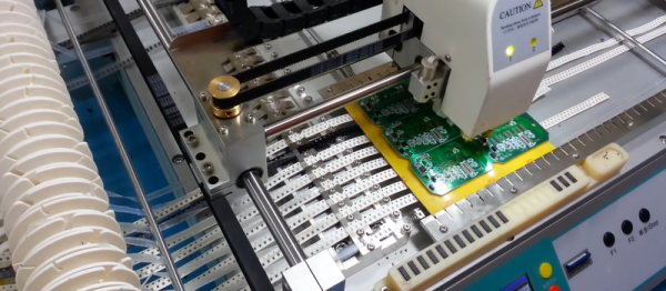
What is so special about this Bingo ball reader? It may seem like an ordinary OCR project at first glance; a camera captures the image and OCR software recognizes the number. Simple as that. And it works without problems, like every simple gadget should.

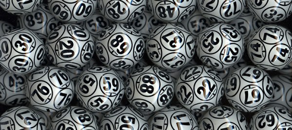
But then again, maybe it’s not that simple. Numbers are scattered all over the ball, so they have to be located first, and the best candidate for reading must be selected. Then, numbers are painted onto a sphere rather than a flat surface, sometimes making them deformed to the point where their shape has to be recovered first. Also, the angle of reading is not fixed but somewhere on a 360° scale. And then we have the glare problem to boot, as Bingo balls are so shiny that every light source reflects as a saturated bright spot.

So, is that all of it? Well, almost. The task is supposed to be performed by an embedded microcontroller, with limited speed and memory, yet the recognition process for one ball has to be fast — 500 ms at worst. But that’s just one part of the process. The project includes the pipelined mechanism which accepts the ball, transports it to be scanned by the OCR and then shot by the public broadcast camera before it gets dumped. And finally, if the reading was not reliable enough, the ball has to be subtly rotated so that the numbers would be repositioned for another reading attempt.

Despite these challenges I did manage to build this system. It’s fast and reliable, and I discovered some very interesting tricks along the way. Take a look at the quick demo video below to get a feel for the speed, and what the system “sees”. Then join me after the break to dive into the details of this interesting embedded build.

Continue reading “Reading Bingo Balls With Microcontrollers”

HDMI Out On The Gameboy Advance

The Gameboy line of handheld systems from Nintendo have been wildly popular, but lack one major thing – a video output. This can be troublesome if you’d like to view the games on a bigger screen, for more comfortable gaming sessions or detail work like producing chiptunes. One option is to use the Gameboy Player for the Gamecube, however that system’s age means you’re out of luck if you want a crisp, clear picture on a modern digital display. Wouldn’t it be great if you could get HDMI output from a Gameboy Advance Instead?

A family resemblance?

When it comes to working with video signals, FPGAs can’t be beat. [Stephen] leverages an FPGA in this project to read the GBA’s video signals and convert them to the modern digital format. Unfortunately, it’s not a seamless install – limited space means the GBA’s screen must be entirely removed, replaced with the adapter in a manner resembling the terrifying Facehugger.

Packaging aside, the output from the device is nothing short of stunning – the graphics are absolutely crystal clear when displayed on a modern HDMI television. This is because the FPGA is capturing the exact digital output from the GBA, and piping it out as HDMI – there’s no analog fuzziness, conversions or noise to spoil the image. Output is a tasty 1280×720, upscaled from the GBA’s original resolution. For more details, check out the forum thread where [Stephen] runs through the build.

The only thing missing  is details – we’d love to know more about the exact hardware used, and any trials and tribulations during the build! As far as we can tell, the build doesn’t stop at just video – a SNES controller is used instead of the original buttons, and we have a feeling sound is being passed over the HDMI channel as well sound is piped to the TV from the GBA’s headphone port.

It’s great to see these projects for old hardware come out – modern hardware has the muscle to achieve things previously unthinkable on retro consoles. We’ve seen similar projects before – like adding VGA to an original Game Boy.

Continue reading “HDMI Out On The Gameboy Advance”

Need For New Hobby Leads To Stone Marbles

[Tom Lange] said he was looking for a new hobby when he saw a marble made out of stone and wondered what goes into making one for himself. Fast forward three years and he set up shop at the Madison Mini Maker Faire to show off the tools he built and the fascinating glossy orbs he’s produced. Read on to see the awesome process he uses to turn a hunk of stone into a perfect marble.

Continue reading “Need For New Hobby Leads To Stone Marbles”

Designing For Fab: A Heads-Up Before Designing PCBs For Professional Assembly

Designing pcbs for assembly is easy, right? We just squirt all the footprints onto a board layout, connect all the traces, send out the gerbers and position files, and we’re done–right?

Whoa, hold the phone, there, young rogue! Just like we can hack together some working source code with variables named after our best friends, we can also design our PCBs in ways that make it fairly difficult to assemble.

However, by following the agreed-upon design specs, we’ll put ourselves on track for success with automated assembly. If we want another party to put components on our boards, we need to clearly communicate the needed steps to get there. The best way to do so is by following the standards.

Proper Footprint Orientation

Now, for a momImage Credit: https://encrypted-tbn2.gstatic.com/images?q=tbn:ANd9GcQBEztpnSxpN_IRjq3y8GbetrMHKuoSu_s6myiFOHilL2FlQKyLrgent, let’s imagine ourselves as the tip of a vacuum pickup tool on a pick-and-place machine. These tools are designed to pick up components on the reel from their centroid and plunk them on their corresponding land pattern. Seems pretty straightforward, right? It is, provided that we design our footprints knowing that they’ll one day come face-to-face with the pick-and-place machine.

To get from the reel to the board, we, the designers, need two bits of information from out part’s datasheet: the part centroid and the reel orientation.

The part centroid is an X-Y location that calls out the center-of-mass of the part. It basically tells the machine: “pick me up from here!” As designers, it’s our responsibility to design all of our footprints such that the footprint origin is set at the part’s centroid. If we forget to do so, the pick-and-place will try to suck up our parts from a location that may not stick very well to the package, such as: the corner.

Continue reading “Designing For Fab: A Heads-Up Before Designing PCBs For Professional Assembly”

[Hari] Prints An Awesome Spider Robot

Although we have strong suspicions that the model’s designer failed entomology, this spider robot is very cool. [Hari Wiguna] made one, and is justifiably thrilled with the results. (Watch his summary on YouTube embedded below.)

Thanks to [Regis Hsu]’s nice design, all [Hari] had to do was order a hexapod’s dozen 9g servos for around $20, print out the parts, attach an Arduino clone, and he was done. We really like the cutouts in the printed parts that nicely fit the servo horns. [Hari] says the calibration procedure is a snap; you run a sketch that sets all the servos to a known position and then tighten the legs in place. Very slick.

The parts should print without support on basically any printer. [Hari]’s is kinda janky and exhibits all sorts of layer-to-layer irregularities (sorry, man!) but the robot works perfectly. Which is not to say that [Hari] doesn’t have assembly skills — check out the world’s smallest (?) RGB LED cube if you think this guy can’t solder. Of course, you can entirely sidestep the 3D-printed parts and just fix a bunch of servos together and call it a robot. It’s harder to make building a four-legger any easier than these two projects. What are you waiting for?

Continue reading “[Hari] Prints An Awesome Spider Robot”

Flying The First Open Source Satellite

The Libre Space Foundation is an organization dedicated to the development of libre space hardware. It was born from the SatNOGS project — the winners of the first Hackaday Prize — and now this foundation is in space. The Libre Space Foundation hitched a ride on the Orbital ATK launch yesterday, and right now their completely Open Source cube sat is on its way to the International Space Station.

The cube sat in question is UPSat, a 2U cubesat that is completely Open Source. Everything from the chassis to the firmware is completely Open, with all the source files hosted on GitHub.

UPSat is currently on its way to the International Space Station stowed in an Orbital ATK Cygnus cargo spacecraft. From here, the UPSat will be unloaded by members of the current ISS expedition and deployed with help from NanoRacks. Basically, the first Open Source satellite will be tossed overboard from the International Space Station. If you want to listen in on the data UPSat is beaming down, build a SatNOGS ground station and tune into 435.765 MHz. With a good antenna, you should be able to hear it when the ISS is in the sky, or a few times a week.

You can check out the launch of the Cygnus the UPSat is flying on in the video below. NASA also recorded a 360° video from the launch pad that unfortunately cuts out in the first few seconds after launch.

Continue reading “Flying The First Open Source Satellite”

Discontinued Nintendo Consoles And Raspberry Pis

Nintendo has discontinued a Classic gaming console. It’s a pity, yes, but with the release of Nintendo’s new gaming console, they probably have bigger fish to fry. That doesn’t mean these discontinued Nintendo consoles will die a slow, miserable death locked away in a closet; at least one of them will live on with the heart of a Raspberry Pi.

This is a project [Liam] has been working on since 2012, just after he got the first edition of the Raspberry Pi. While some people were figuring out how to stuff the Pi inside a Nintendo Entertainment System or a Super Nintendo Entertainment System, [Liam] decided to embed the Pi inside a console of a more recent vintage: the Nintendo GameCube.

The first phase of this project was simply to get the Pi running inside the enclosure of the non-working GameCube he picked up. The power supply in this console was well designed, and after a quick perusal through some online documentation, [Liam] found a stable 5V with enough amps to power the Pi. After ripping out the internals of this console with the help of a quickly hacked together ‘Nintendo screwdriver’, [Liam] had a perfectly functional Pi enclosed in a Nintendo chassis.

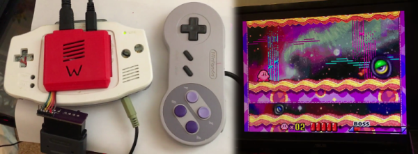
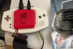
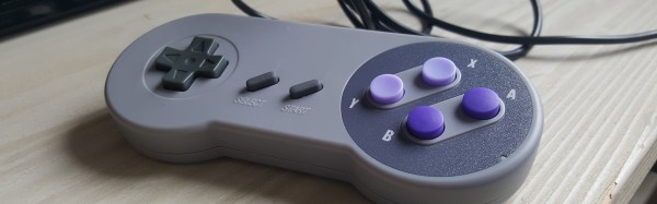
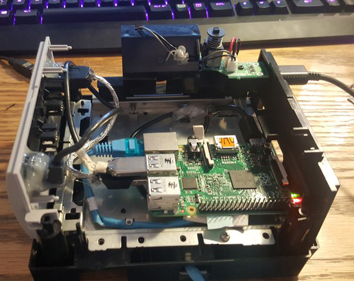
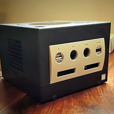
Time marches on, and after a while, the Raspberry Pi 2 was released. By this time, retro emulation was hitting the big time, and [Liam] decided it was time for an upgrade. He disassembled this Nintendo console again, routed new wires and inputs to the original controller ports, and used a Dremel to route a few holes for the HDMI and SD card slot.

With the addition of a few SNES-inspired USB controllers, RetroPi, and a few ROMs, [Liam] has a wonderful console full of classic emulation goodness, packaged in an enclosure Nintendo isn’t making any more.