Hand soldering of surface mount components is a bread-and-butter task for anyone working with electronics in 2024. So many devices are simply no longer available in the older through-hole formats, and it’s now normal for even the most homebrew of circuits to use a PCB. But how do you solder your parts? If like us you put a blob of solder on a pad and drop the part into it, then [Mr. SolderFix] has some advice on a way to up your game.
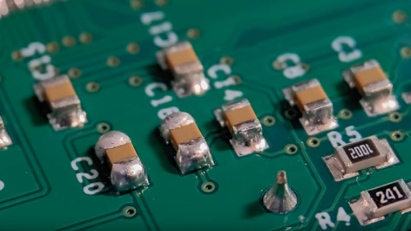
The blob of solder method leaves a little more solder on the part than is optimal, sometimes a bulbous lump of the stuff. Instead, he puts a bit of flux on the pad and then applies a much smaller quantity of solder on the tip of his iron, resulting in a far better joint. As you can see in the video below, the difference is significant. He starts with passives, but then shows us the technique on a crystal, noting that it’s possible to get the solder on the top of these parts if too much is used. Yes, we’ve been there. Watch the whole video, and improve your surface mount soldering technique!
He’s someone we’ve featured before here at Hackaday, most recently in lifting surface mount IC pins.