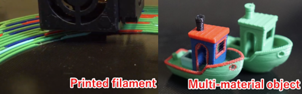
When 3D pens first became available, many assumed them to be gimmicky or part of a general fad that would eventually die out. Like most revolutionary technologies, though, they’ve found a firm foothold, especially in the art community where the ability to 3D print in freehand is incredibly valuable. There are still some shortcomings with the technology, though, but [tterev3] recently tore into a 3doodler pen to make some necessary upgrades.
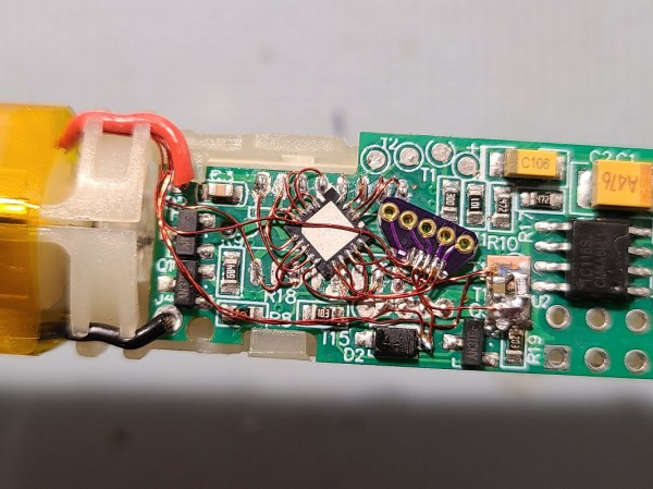
First, this pen has some design choices that are curious, to say the least. The cooling fan runs regardless of temperature, and it has pushbuttons for start and stop rather than a momentary button that controls the extrusion. To fix these issues, as well as change the filament size, improve the cooling, and provide greater control over the extrusion speed, [tterev3] completely rewrote the firmware, changed the microcontroller on the PCB, and made several hardware upgrades to accommodate these changes. He also went ahead and installed a USB-C port for charging, which should be standard practice on all low-voltage consumer electronics by now anyway.
The detail work on this project is impressive, given the small size of the pen itself and the amount of precision hardware needed to make the changes. Especially regarding the replacement of the microcontroller on the board itself, which is an impressive feat even without the incredibly small dimensions. The firmware upgrade is available on his GitHub page as well if you have your own 3doodler that needs modifications, and if you’re still struggling to find uses for these handy devices, we’ve seen them used with interesting effect to build drones.