Americans love their coffee. The Brits adore their tea. In South America, the number one way to get through the day is with yerba mate, a tea made from the yerba plant. It is typically shared in a social setting, with one person preparing the beverage for everyone to enjoy. Although caffeine certainly deserves a ceremony, it never needs one. Hit the streets and you’ll see people everywhere with a thermos under one arm, keeping water hot and ready to refill the cup of mate in their hand.
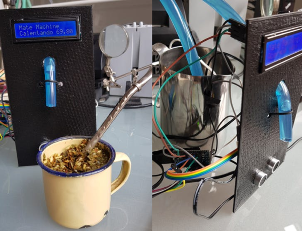
The Stanley vacuum thermos is quite a popular choice for drinkers on the go, but the Argentinian government recently placed new restrictions foreign imports. [Roni Bandini] decided to build a minimum viable mate machine so he always has perfectly hot water on tap.
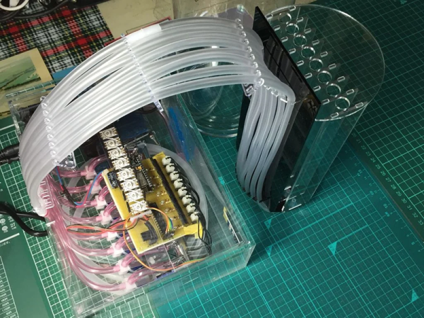
An Arduino Nano heats the water and displays the rising temperature on an LCD screen. When the temperature is just right, the display asks for your cup. An ultrasonic sensor detects the cup and dispenses a certain amount of water determined in the sketch. Yerba leaves can be used a few times before losing their flavor, so the machine keeps track and lets him know when it’s time to replace them. You can sip on a brief demo after the break.
Let’s say you don’t have perfectly-prepared mate, and it always comes out too hot. That’s better than too cold, but still not ideal. Why not make a temperature-sensing coaster that alerts you when it has cooled to perfection?
Continue reading “Minimalist Mate Maker Keeps You Caffeinated”