[Sprite_TM] OHM2013 Talk: Hacking Hard Drive Controller Chips

Even if he hadn’t done any firmware hacking on this hard drive [Sprite_TM’s] digital exploration of the controller is fascinating. He gave a talk at this year’s Observe, Hack, Make (OHM2013) — a non-commercial community run event in the Netherlands and we can’t wait for the video. But all the information on how he hacked into the three-core controller chip is included in his write up.

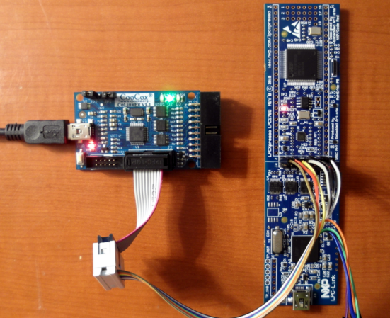
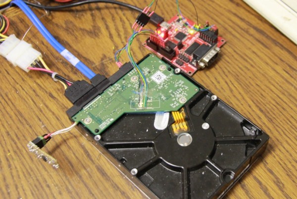
[Sprite_TM] mentions that you’re not going to find datasheets for the controllers on these drives. He got his foot in the door after finding a JTAG pinout mentioned on a forum post. The image above shows his JTAG hardware which he’s controlling with OpenOCD. This led him to discover that there are three cores inside the controller, each used for a different purpose. The difference between [Sprite_TM’s] work and that of mere mortals is that he has a knack for drawing surprisingly accurate conclusions from meager clues. To see what we mean check out the memory map for the second core which he posted on page 3 of his article.

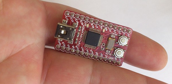
Using JTAG he was able to inject a jump into the code (along with a filler word to keep the checksum valid) and run his own code. To begin the firmware hacking portion of the project he pulled the flash ROM off of the board and installed it on that little board sticking out on the left. This made it easy for him to backup and reflash the chip. Eventually this let him pull off the same proof of concept as a firmware-only hack (no JTAG necessary). He goes onto detail how an attacker who has root access could flash hacked firmware which compromises data without any indication to they system admin or user. But we also like his suggestion that you should try this out on your broken hard drives to see if you can reuse the controllers for embedded projects. That idea is a ton a fun!

When we were poking around the OHM2013 website (linked above) we noticed that the tickets are sold out; good for them! But if you were still able to buy them they take Bitcoin as one payment option. Are there any other conferences that allow Bitcoin for registration?

BeagleBone SensorCape Lets You Measure Just About Anything

beaglebone-sensor-cape

Here’s another entry in the 2013 Intern Design Challenge which motivates summer Interns at Texas Instruments to build something cool for one of a handful of embedded platforms. This entry, developed by [Michael Leonard] is a cape for the BeagleBone Black which has footprints for a bunch of different sensors.

Use it to turn your BeagleBone into a weather station by populating the temperature, pressure, and humidity sensors. Or perhaps you’d prefer an IMU for your next quadcopter by populating the MPU-9150 chip on the pad labeled ‘9-Axis’. This part is an accelerometer, gyroscope, and digital compass all in one. There’s also room for a light sensor and an IR remote control receiver, with the large square pads on the right servung as breakouts for input buttons. If you want all the nitty-gritty on the sensors he designed for [Michael’s] done a great job of compiling a reference manual for the board.

[Michael] didn’t send us a link until he saw the retro-gaming cape we featured on Tuesday. Come on people! Don’t hide in the basement and build stuff unless you’re going to tell us about it.

Continue reading “BeagleBone SensorCape Lets You Measure Just About Anything”

How To Use CoIDE With LPCXpresso Board

lpcxpresso-coocox

[James Lynch] picked up an LPCXpresso board because he wanted play around with ARM processors. The board, which is shown on the right, provides everything you need to get started. It even ships with a free IDE. But unfortunately the free version of that Code Red IDE is size limited. If he wanted to remove the restriction he would have to pony up $999 for a licensed version. A company might not think twice about this payment, but in the hobby realm that’s simply out of the question. Instead, [James] figured out how to use the CooCox programmer with the LPCXpresso hardware. To get at his 59-page guide on the process follow that link and hit the “Download Zip” button in the lower right for a copy of the PDF file.

The hack comes in two parts. First you need to alter the LPCXpresso board. There is a center line that separates the dev board form the debugger/programmer. These are connected with solder bridges between rows of a dual pin-header. [James] removed the bridges and added said pin header. This allows him to jumper the connections and use it as normal, or attach it to his CooCox programmer as seen above. The second part of the project walks through the process of getting the free CoIDE (also based on Eclipse) to compile and program code for the LPCXpresso.

We’ve seen this dev board here and there, notably in an oscilloscope build.

ARM Dev Board With USB Uploading

[George and Bogdan] wrote in to tell us about a cool Kickstarter they’ve been working on. It’s called the MatchboxARM, and like other tiny-yet-powerful ARM dev boards floating around, this one features a very fast and capable processor and more than enough pins for just about any project. One interesting feature of this board, however, makes it stand out from the pack: it has a USB mass storage-based bootloader, meaning uploading new code is as easy as a drag and drop.

This isn’t the first dev board we’ve seen to sport this feature: the Stellaris Launchpad has had this for a while and even the lowly ATtiny85, in the form of a Digispark has a mass storage-based bootloader. The MatchboxARM, though, brings this together with a very powerful ARM microcontroller with enough I/Os, ADCs, PWM pins, and I2C and SPI ports for the most complicated projects.

Text Editor Running On Your ARM Project

bare-metal-elua-text-editor

Tired of flashing your embedded project over and over just to tweak a few values? So was [Karl], so he wrote a text editor that runs on his ARM dev board.

Having trouble wrapping your mind around the need for this kind of thing? He’s actually playing around with eLua, the embedded version of the Lua programming language. In this case the program files are being stored on an SD card. But still, moving that back and forth between computer and embedded project gets old quickly. So he invested the time to write a rudimentary text editor that he interfaces through this terminal window. Above you can see the help screen which lays out all of the applications features. Right now it sounds like the only gotcha for this is the amount of RAM it needs to run. As it stands, the editor will now work an mbed board, but it works just fine on an STM Discovery.

Ambilight Clone Uses Video Pass-through; Needs No Computer

To the best of our knowledge all of the Ambilight clones we’ve covered over the years have one thing in common. They need a computer to do the image processing. This one is different. The PCB seen on the left right is all you need for the video processing. The project is called SCIMO and is the handiwork of a hacker named [Keiang].

There are only few times that the DRM built into the HDMI standard has pissed us off. This is one of them. Because of HDCP and licensing issued revolving around HDMI [Keiang] didn’t use HDMI pass through. Instead he uses an HDMI to S-Video converter. This board acts as an S-Video pass through, analyzing the signal using an STM32 ARM chip before the video signal continues on to the television. It still produces a respectable picture, but wouldn’t it have been cleaner if he could have gone with the HDMI standard?

UPDATE: Thanks for the comments on this. It looks like the TV is getting an HDMI signal. The board is fed by the HDMI to S-Video converter which itself is getting HDMI in parallel with the television thanks to a splitter.

Where other examples use Boblight on a PC for processing this manages to do so as a standalone embedded system. It also offers quite a bit of flexibility when it comes to choosing the LEDs, supporting pixels that use DMX512, WS28xx, or TM18xx protocols.

Continue reading “Ambilight Clone Uses Video Pass-through; Needs No Computer”

Simon Says Learn How To Program ARM Chips

barebones-simon-says

This breadboard version of a Simon Says game is a great way to try your skills on a new microcontroller platform. The eight-pin chip seen in the center of the board is an LPC810 microcontroller which [Hartmut Wendt] is just getting started with. It’s a rare example of a low-pin count DIP package for an ARM device (Cortext M0). The breadboard friendly footprint makes it easy to work with, but you could pull off the same build with a dev board like one of the STM discovery offerings or the Stellaris Launchpad boards.

Why is this a good way to learn? It involves input, output, and generating waveforms which we’d assume means timers (we didn’t dig through the source code which is available form the page linked above). Each colored button has a matching LED which blinks out the pattern which you must replicate to keep the game going; you know how Simon Says works, right?. At the same time a different pitch is played by the speaker on the right.

Another good exercise would be to take [Hartmut’s] code and port it for a different chip, be it ARM or otherwise.

Continue reading “Simon Says Learn How To Program ARM Chips”