Controlling Analog with SPI

We Assume Control: SPI And A Digital Potentiometer

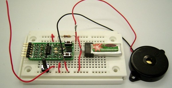
In the last video I demonstrated a Universal Active Filter that I could adjust with a dual-gang potentiometer, here I replace the potentiometer with a processor controlled solid-state potentiometer. For those that are too young to remember, we used to say “solid-state” to differentiate between that and something that used vacuum tubes… mostly we meant you could drop it without it breakage.

The most common way to control the everyday peripheral chips available is through use of one of the common Serial Protocols such as I2C and SPI.  In the before-time back when we had only 8 bits and were lucky if 7 of them worked, we used to have to memory map a peripheral or Input/Output (I/O) controller which means we had to take many control and data lines from the microprocessor such as Data, Address, Read/Write, system clocks and several other signals just to write to a couple of control registers buried in a chip.

Nowadays there is a proliferation of microcontrollers that tend to have built-in serial interface capability it is pretty straightforward to control a full range of peripheral functions; digital and analog alike.  Rather than map each peripheral using said data and address lines,which is a very parallel approach,  the controller communicates with peripherals serially using but a handful of signal lines such as serial data and clock. A major task of old system design, mapping of I/O and peripherals, is no longer needed.

Continue reading “We Assume Control: SPI And A Digital Potentiometer”

remote circuit board

Ultimate Remote Is Ultimate

[Joedefa] had a Griffin Beacon Universal Remote that was collecting dust, and decided that it needed to stop collecting dust. He had a growing number of wireless devices in his house and found himself in need of a remote to control them all. The Griffin Beacon fit the bill, but most of his lights and outlets were RF controlled. So he did what hackers do best… broke out the screw driver and soldering iron and rewired it!

[Joedefa] is using an Attiny85 as the brains between an infrared LED and a RF transmit module (if anyone can identify the source of this module, please let everyone know in the comments).  A pair of red and green LEDs lets him know if the remote has received commands successfully.

It’s always nice to see a discontinued product made useful once more with a little ingenuity and an Arduino some hacking skill. Hat’s off to [Joedefa] for a righteous hack!

An ATTiny Bluetooth Board

Since just about everyone who would be interested in electronics has a decent cellphone now, there’s an idea that we don’t need USB or weird serial adapters anymore. Bluetooth LE is good enough for short-range communication, and there are a ton of boards and Kickstarter projects out there that are ready to fill the need.

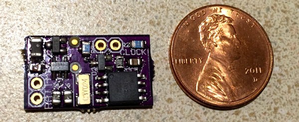
[Michah] has built what is probably the lowest-spec and cheapest BTLE board we’ve ever seen. It’s really just an ATTiny85 – a favorite of the crowd that’s just slightly above Arduino level – and an HM-10 Bluetooth 4.0 Low Energy module.

This board was developed as a means to connect sensors for a vintage motorcycle to an iOS device for display and data logging. A small, cheap board was needed that could be powered by a LiPo battery, and [Micah] created a board that fit his needs perfectly.

Four of the six IO pins on the ‘Tiny85 are broken out on a pin header; two are used to communicate with the BTLE module. It’s simple, fairly cheap, and can be powered by a battery. Exactly what you need if you want a wireless sensor board. All the files can be found in the Git repo and everything is open source. Not bad.

DIY Camera Shutter Control

Full SHTTTRRR Control Lets You Take Your Time…

[Glitchmaker] loves photography and wrote in to tell us about his newest project. He has a Canon 1000D camera but, unfortunately, it does not have time lapse capability. So, instead of shelling out a chunk of change for a new camera [Glitchmaker] decided to make an external shutter control device that can continue to instruct the camera to take photos at predetermined intervals. He calls his project: SHTTTRRR. You didn’t think that meant something else, did you?

You can see the unassuming box above, there is just enough stuff packed in there to get the job done, nothing extra or fancy. Luckily, the Cannon camera has a remote shutter input jack that only requires connecting one pin to another in order to take a photo. Inside the box is an ATTINY45 microcontroller. It reads the button pushes from the single panel-mounted button and calculates the time between two button presses. That time between button presses determines the frequency of the photos taken. At the appropriate times, the ATTINY45 signals a transistor to connect the two appropriate pins on the camera’s remote shutter input jack. The device continues to tell the camera to take photos until it is shut off. The result is a series of time-lapse photos that was previously not possible on that camera!

This is a simple project that solves a problem and gets the job done. What’s better than that? [Glitchmaker] is proud of the SHTTTRRR he made and also learned a bunch about programming the ATTINY45 along the way. Check a video of it working after the break.

Continue reading “Full SHTTTRRR Control Lets You Take Your Time…”

Holiday Cheer From The ATtiny13

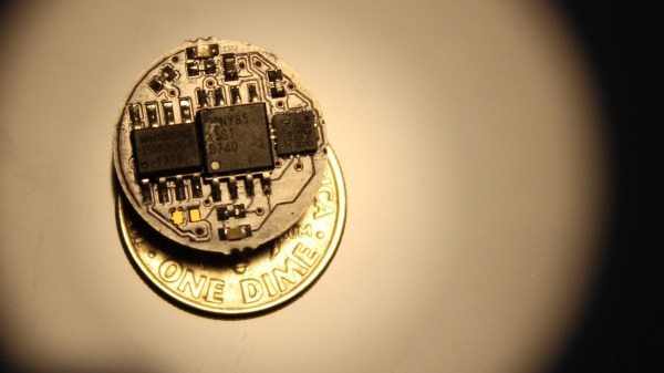
There are smaller microcontrollers than the ATtiny13. Some ARM chips will fit on the head of a large pin, and even in Atmel world, the ATtiny10 comes in a tiny SOT-23-6 package – a size normally reserved for surface mount transistors. The ‘tiny13, though, can be programmed with just about any ISP and comes in an 8-pin DIP. It’s the bare minimum if you’re looking to break out of the world of Arduino, and you can do some pretty cool things with it, like playing some holiday audio with an SPI Flash chip.

[Vinod] tried opening up a cheap camera pen, but in the course of disassembly a few traces broke. He was now left with a 4Mbit SPI Flash chip. This was obviously the time to investigate what could be done with a small microcontroller and a huge amount of Flash. and the Attiny13 audio player was born.

The circuit uses one PWM for audio out, and reads audio directly from the Flash chip. The UART on board the ‘tiny13 is used to update the Flash, and there’s also a switch to select between play and record. If you’re counting, that means there are 4 pins for the Flash, 2 pins for the UART, 1 for the switch, one for the audio output, and the power and ground rails, all in an 8-pin package. That’s a pretty cool way to use one pin for two different functions.

You can check out a video of the project in action below.

Continue reading “Holiday Cheer From The ATtiny13”

Class D Amp With An H-Bridge

Class D amps are simple – just take an input, and use that to modulate a square wave with PWM. Send this PWM signal to a MOSFET or something, and you have the simplest class D amp in existence. They’re so simple, you can buy a class D amp chip for $3, but [George] thought that would be too easy. Instead, he built his own with an ATTiny and an H-bridge motor driver. No surprise, it works, but what’s interesting is what effect the code on the ATtiny can have on the quality of the audio coming out of the speaker.

The microcontroller chosen for this project was the ATtiny 461, a part we don’t see much, but still exactly what you’d expect from an ATtiny. The heavy lifting part of this build is an L298 chip found on eBay for a few dollars. This dual H-bridge is usually used for driving motors, but [George] found a home for it in the power section of an amplifier.

The ATtiny is clocked at 16 MHz, making the ADC clock run at 1 MHz. A 10-bit precision conversion takes place, and this value sets the PWM duty cycle. Timer1 in the chip is set up to run at 32 MHz, and by counting this timer up to 1023 gives this amp its PWM cycle speed of 31.25 kHz. That’s right in the neighborhood of what a class D amp should run at, and the code is only about 30 lines. It can’t get simpler than that.

[George] put up a video of this amp in operation, and despite not following the standard design of a Class D amp, it sounds pretty good. You can see that video below.

Continue reading “Class D Amp With An H-Bridge”

Transferring Audio To An AVR At 12kbps

Back in the bad ‘ol days of computing, hard drives cost as much as a car, and floppy drives were incredibly expensive. The solution to this data storage problem offered by all the manufacturers was simple – an audio cassette. It’s an elegant solution to a storage problem, and something that has applications today.

[Jari] was working on a wearable message badge with an 8-pin ATTiny. To get data onto this device, he looked at his options and couldn’t find anything good; USB needs two pins and the firmware takes up 1/4 of the Flash, UART isn’t available on every computer, and Bluetooth and WiFi are expensive and complicated. This left using audio to send digital data as the simplest solution.

[Jari] went through a ton of Wikipedia articles to figure out the best modulation scheme for transferring data with audio. What he came up with is very simple: just a square wave that’s changed by turning a pin off and on. When the audio is three samples long without crossing zero, the data is 0. When it’s five samples long without crossing zero, the data is 1. There’s a 17-sample long sync pulse, and with a small circuit that acts as a zero crossing detector, [Jari] had a simple circuit that would transfer data easily and cheaply.

All the code for this extremely cheap modem is available on GitHub.