A Forgotten Photographic Process Characterised

Early photography lacked the convenience of the stable roll film we all know, and instead relied on a set of processes which the photographer would have to master from film to final print. Photographic chemicals could be flammable or even deadly, and results took a huge amount of work.

The daguerreotype process of using mercury to develop pictures on polished metal, and the wet-collodion plate with its nitrocellulose solution are well-known, but as conservators at the British National Archives found out, there was another process that’s much rarer. The Pannotype uses a collodion emulsion, but instead of the glass plate used by the wet-plate process it uses a fabric backing.

We know so much about the other processes because they were subject to patents, but pannotype never had a patent due to a disagreement. Thus when the conservators encountered some pannotypes in varying states of preservation, they needed to apply modern analytical techniques to understand the chemistry and select the best methods of stabilization. The linked article details those analyses, and provides them with some pointers towards conserving their collection. We look forward to someone making pannotype prints here in 2025, after all it’s not the first recreation of early photography we’ve seen.

Protocol Analyzer Remembered

Anyone will tell you that as hard as it is to create a working system, the real trick is making two systems talk to each other, especially if you created only one or none of them. That’s why tools that let you listen in on two systems talking are especially valuable.

If you were a well-funded lab back in the RS232 days, you might have an HP4957A protocol analyzer. The good news is that if you still use RS232, these kinds of things are now cheap on the surplus market. [IMSAI Guy] got one of these decidedly cool devices and shows it to us in the video below.

The look of these was pretty neat for their time—a folded-up instrument with a cute keyboard and a CRT-100. You can load different interpreters from ROM to RAM, such as the VT-100, which is essentially an application for the device. Of course, now you could rig one of these up in a few minutes with a PC or even a Pi Pico. But it wouldn’t have the same charm, we are sure you would agree.

You can find a lot of old RS232 gear around, from breakout boxes to advanced sniffers like this one. Too bad we couldn’t afford them when we really needed them.

This could be handy if you have a lot of ports. Either real or virtual. Or, do it yourself.

Continue reading “Protocol Analyzer Remembered”

Contagious Ideas

We ran a story about a wall-mounted plotter bot this week, Mural. It’s a simple, but very well implemented, take on a theme that we’ve seen over and over again in various forms. Two lines, or in this case timing belts, hang the bot on a wall, and two motors drive it around. Maybe a servo pulls the pen in and out, but that’s about it. The rest is motor driving and code.

We were thinking about the first such bot we’ve ever seen, and couldn’t come up with anything earlier than Hektor, a spray-painting version of this idea by [Juerg Lehni]. And since then, it’s reappeared in numerous variations.

Some implementations mount the motors on the wall, some on the bot. There are various geometries and refinements to try to make the system behave more like a simple Cartesian one, but in the end, you always have to deal with a little bit of geometry, or just relish the not-quite-straight lines. (We have yet to see an implementation that maps out the nonlinearities using a webcam, for instance, but that would be cool.) If you’re feeling particularly reductionist, you can even do away with the pen-lifter entirely and simply draw everything as a connected line, Etch-a-Sketch style. Maslow CNC swaps out the pen for a router, and cuts wood.

What I love about this family of wall-plotter bots is that none of them are identical, but they all clearly share the same fundamental idea. You certainly wouldn’t call any one of them a “copy” of another, but they’re all related, like riffing off of the same piece of music, or painting the same haystack in different lighting conditions: robot jazz, or a study in various mechanical implementations of the same core concept. The collection of all wall bots is more than the sum of its parts, and you can learn something from each one. Have you made yours yet?

(Fantastic plotter-bot art by [Sarah Petkus] from her write-up ten years ago!)

Recreating The Analog Beauty Of A Vintage Tektronix Oscillator

Tektronix must have been quite a place to work back in the 1980s. The company offered a bewildering selection of test equipment, and while the digital age was creeping in, much of their gear was still firmly rooted in the analog world. And some of the engineering tricks the Tek wizards pulled off are still the stuff of legend.

One such gem of analog design was the SG505, an ultra-low-distortion oscillator module that [Paul] is trying to replicate with modern parts. That’s a tall order since not only did the original specs on this oscillator call for less than 0.0008% total harmonic distortion over a frequency range of 20 Hz to 20 kHz, but a lot of the components it used are no longer manufactured. Tek also tended to use a lot of custom parts, especially mechanical ones like the barrel switch used to select attenuation levels in the SG505, leaving [Paul] no choice but to engineer his way around them.

So far, [Paul] has managed to track down most of the critical components or source suitable substitutes. One major win was locating the original J-FET Tek used in the oscillator’s AGC circuit. One part that’s proven more elusive is the potentiometer that Tek used to adjust the frequency; who knew that finding a dual-gang precision wirewound 10k single-turn pot with no physical stop would be such a chore?

[Paul] still seems to be very much in the planning stages of this project yet, and that’s probably for the best since projects such as these live and die on proper planning. We’re keen to see how this develops, and we’re very much looking forward to seeing the FFT results. We also imagine he’ll be busting out his custom curve tracer at some point in the build, too.

Pictures From A High Altitude Balloon

How do you get images downlinked from 30 km up? Hams might guess SSTV — slow scan TV — and that’s the approach [desafloinventor] took. If you haven’t seen it before (no pun intended), SSTV is a way to send images over radio at a low frame rate. Usually, you get about 30 seconds to 2 minutes per frame.

The setup uses regular, cheap walkie-talkies for the radio portion on a band that doesn’t require a license. The ESP32-CAM provides the processing and image acquisition. Normally, you don’t think of these radios as having a lot of range, but if the transmitter is high, the range will be very good. The project steals the board out of the radio to save weight. You only fly the PC board, not the entire radio.

If you are familiar with SSTV, the ESP-32 code encodes the image using Martin 1. This color format was developed by a ham named [Martin] (G3OQD). A 320×256 image takes nearly two minutes to send. The balloon system sends every 10 minutes, so that’s not a problem.

Of course, this technique will work anywhere you want to send images over a communication medium. Hams use these SSTV formats even on noisy shortwave frequencies, so the protocols are robust.

Hams used SSTV to trade memes way before the Internet. Need to receive SSTV? No problem.

Multi-Divi book with hand thumbing through it

Math, Optimized: Sweden’s Maximal Multi-Divi

Back in the early 1900s, before calculators lived in our pockets, crunching numbers was painstaking work. Adding machines existed, but they weren’t exactly convenient nor cheap. Enter Wilken Wilkenson and his Maximal Multi-Divi, a massive multiplication and division table that turned math into an industrialized process. Originally published in Sweden in the 1910’s, and refined over decades, his book was more than a reference. It was a modular calculating instrument, optimized for speed and efficiency. In this video, [Chris Staecker] tells all about this fascinating relic.

What makes the Multi-Divi special isn’t just its sheer size – handling up to 9995 × 995 multiplications – but its clever design. Wilkenson formatted the book like a machine, with modular sections that could be swapped out for different models. If you needed an expanded range, you could just swap in an extra 200 pages. To sell it internationally, just replace the insert – no translation needed. The book itself contains zero words, only numbers. Even the marketing pushed this as a serious calculating device, rather than just another dusty math bible.

While pinwheel machines and comptometers were available at the time, they required training and upkeep. The Multi-Divi, in contrast, required zero learning curve – just look up the numbers for instant result. And it wasn’t just multiplication: the book also handled division in reverse, plus compound interest, square roots, and even amortizations. Wilkenson effectively created a pre-digital computing tool, a kind of pocket calculator on steroids (if pockets were the size of briefcases).

Of course, no self-respecting hacker would take claims of ‘the greatest invention ever’ at face value. Wilkenson’s marketing, while grandiose, wasn’t entirely wrong – the Multi-Divi outpaced mechanical calculators in speed tests. And if you’re feeling adventurous, [Chris] has scanned the entire book, so you can try it yourself.

Continue reading “Math, Optimized: Sweden’s Maximal Multi-Divi”

Chase Light SAO Shouldn’t Have Used A 555, And Didn’t

Around these parts, projects needlessly using a microcontroller where a simpler design would do are often derided with the catch-all “Should have used a 555,” even if the venerable timer chip wouldn’t have been the ideal solution. But the sentiment stands that a solution more complicated than it needs to be is probably one that needs rethinking, as this completely mechanical chaser light badge Simple Add-On (SAO) aptly demonstrates.

Rather than choosing any number of circuits to turn a strip of discrete lights on and off, [Johannes] took inspiration for his chaser lights from factory automation mechanisms that move parts between levels on steps that move out of phase with each other, similar to the marble-raising mechanism used in [Wintergatan]’s Marble Machine X.

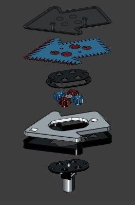
Two thin plates with notches around the edge are sandwiched together inside the 3D printed case of the SAO, between the face and the light source. A small motor and a series of gears rotate the two masks 180° out of phase with each other, which creates the illusion that the light is moving.

It’s pretty convincing; when we first saw the video below, we were sure it was a row of tiny LEDs around the edge of the badge.

Hats off to [Johannes] for coming up with such a clever mechanism and getting it working just in time for Hackaday Europe. If you need to catch up on the talks, we’ve got a playlist ready for you.

Continue reading “Chase Light SAO Shouldn’t Have Used A 555, And Didn’t”