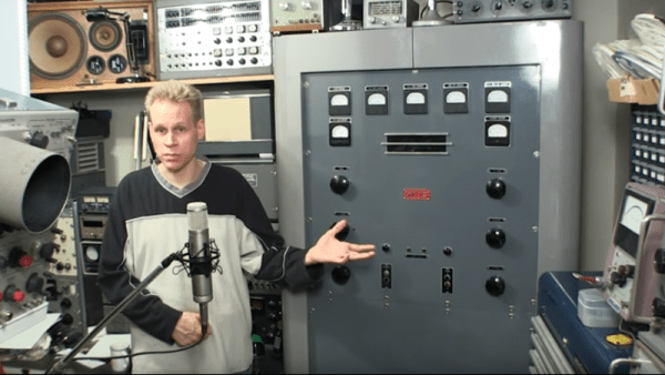
[Mr. Carlson] likes electronics gear. Mostly old gear. The grayer the case, the greener the phosphors, and the more hammertone, the better. That’s why we’re not surprised to see him with a mammoth AM radio station transmitter in his shop. That it’s a transmitter that you can walk into while it’s energized was a bit of a surprise, though.
As radio station transmitters go, [Mr. Carlson]’s Gates BC-250-GY broadcast transmitter is actually pretty small, especially for 1940s-vintage gear. It has a 250 watt output and was used as a nighttime transmitter; AM stations are typically required to operate at reduced power when the ionosphere is favorable for skip on the medium frequency bands. Stations often use separate day and night transmitters rather than just dialing back the daytime flamethrower; this allows plenty of time for maintenance with no interruptions to programming.
If you enjoy old broadcast gear, the tour of this transmitter, which has been rebuilt for use in the ham bands, will be a real treat. Feast your eyes on those lovely old bakelite knobs and the Simpson and Westinghouse meters, and picture a broadcast engineer in white short sleeves and skinny tie making notations on a clipboard. The transmitter is just as lovely on the inside — once the plate power supply is shut down, of course, lest [Mr. Carlson] quickly become [the former late Mr. Carlson] upon stepping inside. Honestly, there aren’t that many components inside, but what’s there is big – huge transformer, giant potato slicer variable caps, wirewound resistors the size of paper towel tubes, and five enormous, glowing vacuum tubes.
It’s a pretty neat bit of broadcasting history, and it’s a treat to see it so lovingly restored. [Mr. Carlson] teases us with other, yet larger daytime transmitters he has yet to restore, and we can’t wait for that tour. Until then, perhaps we can just review [Mr. Crosley]’s giant Cincinnati transmitter from the 1920s and wait patiently.
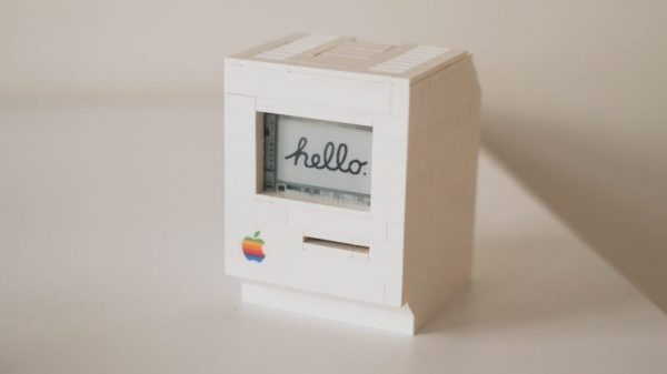
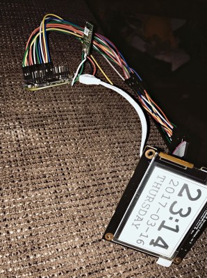 [Jannis Hermanns] couldn’t find a reason to control this outburst of nostalgia for the good old days of small, expensive computers and long hours spent clawing through the LEGO bin to find The Perfect Piece to finish a build. It turns out that the computer part of this replica was the easy part — it’s just an e-paper display driven by a Raspberry Pi Zero. Building the case was another matter, though.