How HP Calculators Communicate Over Infrared

For most people, calculators are cheap and simple devices used for little more than addition and the odd multiplication job. However, when you get into scientific and graphical calculators, the feature sets get a lot more interesting. For example, [Ready? Z80] has this excellent explainer on how HP’s older calculators handle infrared communications.

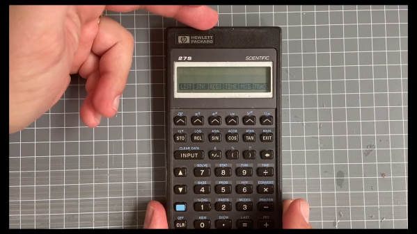
The video focuses on the HP 27S Scientific Calculator, which [Ready? Z80] found in an op-shop for just $5. Introduced in 1988, the HP-27S had the ability to dump screen data over an infrared link to a thermal printer to produce paper records of mundane high-school calculations or important engineering math. In the video, [Ready? Z80] explains the communication method with the aid of Hewlett-Packard’s own journal publication from October 1987, which lays out of the details of “the REDEYE Protocol.” Edgy stuff.

It’s pretty straightforward to understand, with the calculator sending out bursts of data in six to eight pulses at a time, modulated onto a 32.768 KHz square wave as is the norm. [Ready? Z80] then goes a step further, whipping up custom hardware to receive the signal and display the resulting data on a serial terminal. This is achieved with a TEC-1G single-board computer, based on the Z80 CPU, because that’s how [Ready? Z80] does things.

We’ve seen other great stuff from this channel before, too. For example, if you’ve ever wanted to multitask on the Z80, it’s entirely possible with the right techniques.

Continue reading “How HP Calculators Communicate Over Infrared”

Nixie Gear Indicator Shines Bright

When you’re driving a car with a stickshift, it’s pretty easy to keep track of which gear you’re in. That can be a little bit more difficult on something like a motorcycle with a sequential shifter. [decogabry] built a neat gearshift indicator to solve this issue.

An ESP32 devboard is used as the brain of the build. It’s paired with an ELM327 dongle over Bluetooth, which is able to hook into the bike’s ODB diagnostic port to pick up data like engine RPM, wheel speed, and coolant temperature. The first two factors are combined in order to calculate the current gear, since the ratio between engine RPM and wheel speed is determined directly by the gear selection. The ESP32 then commands a Philips ZM1020 Nixie tube to display the gear, driving it via a small nest of MPSA42 transistors. A separate self-contained power supply module is used to take the bike’s 12 volt supply up to the 170 volts needed to run the tube. There is also a small four-digit display used to show status information, RPM, and engine temperature.

Notably,  [decogabry] made this build rather flexible, to suit any bike it might be installed upon. The gear ratios are not hard coded in software. Instead, there is a simple learning routine that runs the first time the system is powered up, which compares RPM and wheel speed during a steady-state ride and saves the ratios to flash.

We’ve featured projects before that used different techniques to achieve similar ends. It’s also interesting to speculate as to whether there’s a motorcycle vintage enough to suit a Nixie display while still having an ODB interface on board as standard. Meanwhile, if you’re cooking up your own neat automotive builds, don’t hesitate to drop us a line.

Robot Sees Light With No CPU

If you ever built a line following robot, you’ll be nostalgic about [Jeremy’s] light-seeking robot. It is a very simple build since there is no CPU and, therefore, also no software.

The trick, of course, is a pair of photo-sensitive resistors. A pair of motors turns the robot until one of the sensors detects light, then moves it forward.

Continue reading “Robot Sees Light With No CPU”

Philips Kid’s Kit Revisited

[Anthony Francis-Jones], like us, has a soft spot for the educational electronic kits from days gone by. In a recent video you can see below, he shows the insides of a Philips EE08 two-transistor radio kit. This is the same kit he built a few months ago (see the second video, below).

Electronics sure look different these days. No surface mount here or even printed circuit boards. The kit had paper cards to guide the construction since the kit could be made into different circuits.

Continue reading “Philips Kid’s Kit Revisited”

Design Of Common Emitter Amplifier

It used to be a rite of passage to be able to do the math necessary to design various bipolar transistor amplifier configurations. This doesn’t come up as often as it used to, but it is still a good skill to have, and [Void Electronics] walks us through a common emitter amplifier in a recent video you can see below.

The input design parameters are the gain and the collector voltage. You also have to pick a reasonable collector current within the range for your proposed device that provides enough power to the load. You also pick a quiescent voltage which, if you don’t have a good reason for picking a different value, will usually be half the supply voltage.

The calculations are approximate since the base-emitter voltage drop will vary by temperature, among other things. But, of course, real resistors won’t have the exact values you want, or even the exact value marked on them, so you need a little flexibility, anyway.

Continue reading “Design Of Common Emitter Amplifier”

39C3: Hacking Washing Machines

Many of us have them, few of us really hack on them: well, here we’re talking about large home appliances. [Severin von Wnuck-Lipinski] and [Hajo Noerenberg] were both working on washing machines, found each other, and formed a glorious cooperation that ended in the unholy union of German super-brands Miele and B/S/H — a Miele washer remote controlled by Siemens’ web app.

This talk, given at the 39th Chaos Communication Congress (39C3), is about much more than the stunt hack, however. In fact, we covered [Severin]’s work on the very clever, but proprietary, Miele Diagnostic Interface a little while ago. But now, he’s got it fully integrated into his home automation system. It’s a great hack, and you can implement it without even opening the box.

About halfway through the talk, [Hajo] takes over, dissecting the internal D-Bus communication protocol. Here, you have to open up the box, but then you get easy access to everything about the internal state of the machine. And D-Bus seems to be used in a wide range of B/S/H/ home appliances, so this overview should give you footing for your own experimentation on coffee machines or dishwashers as well. Of course, he wires up an ESP32 to the bus, and connects everything, at the lowest level, to his home automation system, but he also went the extra mile and wrote up a software stack to support it.

It’s a great talk, with equal parts humor and heroic hacking. If you’re thinking about expanding out your own home automation setup, or are even just curious about what goes on inside those machines these days, you should absolutely give it a watch.

Editor Note: The “S” is Siemens, which is Hackaday’s parent company’s parent company. Needless to say, they had nothing to do with this work or our reporting on it.

A photo of the circuit on a breadboard

Retro Semiconductors: The Silicon Controlled Rectifier

Over on YouTube [Lockdown Electronics] reviews an old bit of kit known as the Silicon Controlled Rectifier (SCR). Invented in the 1950s the SCR is a type of thyristor and they were popular back in the 1970s. They are often replaced these days by the TRIAC and the MOSFET but you might still find some old schematics that call for them and you can still buy them.

The SCR is a three terminal electronic switch which latches on. You apply a signal at the gate which allows the other two pins, the anode and cathode, to conduct; and they continue to do so until power is removed. The silicon inside the device is comprised of three semiconductor junctions, as: PNPN. The P on the left is the anode, the N on the right is the cathode, and the P in the right middle is the gate.

Continue reading “Retro Semiconductors: The Silicon Controlled Rectifier”