Why Build A CNC Mill When You Can Have A Chess Robot Instead?

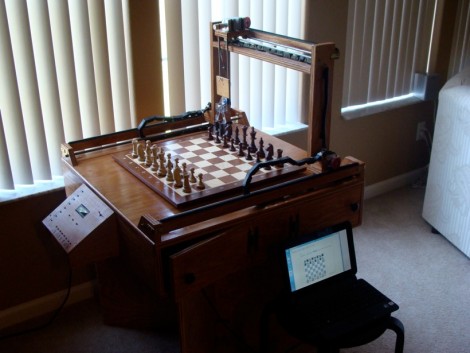
[Patrick McCabe] enjoys the challenge of playing chess against the computer but he wasn’t satisfied with the flat experience of on-screen gaming. No problem, he just built his own gantry-style chess robot that he can play against. Don’t be confused, he still doesn’t have to touch the pieces, but instead uses the dedicated control board seen on the left of the image above. The robotic arm that is mounted on a gantry takes care of moves for both players.

It’s a pretty normal CNC build, using four stepper motors to slide the moving bits along precision rod. An Arduino Mega drives the system, with a PC doing the heavy lifting using a program called My Robot Lab.

We certainly like it that [Patrick] spent a little bit of time making the cabinet and visible parts look nice. Chess is a civilized game and unfinished parts would be out-of-place. We didn’t see it in his writeup, but the one feature we’re really hoping he has implemented is the ability to have the robot automatically reset the board at the beginning of a game.

As you might have guess, you’ll find embedded video after the break.

Continue reading “Why Build A CNC Mill When You Can Have A Chess Robot Instead?”

BAMF2011: Lasersaur Is One BIG Laser Cutter!

Psst…wanna buy a laser cutter, but not ready to sell your internal organs? Nortd Labs’ Lasersaur project aims to create an open source large-format laser cutter/engraver that undercuts (har har!) the cost of commercial models by an order of magnitude.

Continue reading “BAMF2011: Lasersaur Is One BIG Laser Cutter!”

Making A 3D Printer Work Wirelessly

Looking for more ways to enhance his 3D printer, [JJ] decided to make it wireless. He got his hands on some $10 Bluetooth modules and figured this would be just the thing to make the link with his laptop.

They came as surface mount modules, so the first thing he had to do was develop a breakout board that he could patch into his Ultimaker 3D printer. This provided a nice opportunity as he needed to do some level converting to make the 3.3V module play nicely with his 5V CNC electronics. The first version of the board turned out well but he had really a poor communications range. The second version, which is pictured above, hangs the module’s antenna off the edge of the breakout board and works a lot better.

We’ve embedded a clip after the break that walks through the development of this board. [JJ] shared the Eagle CAD files as a megaupload link, but we’ve also mirrored the file after the break for your convenience.

Continue reading “Making A 3D Printer Work Wirelessly”

Adding A Tachometer To The SX2 Mini Mill

sx2_mill_tach

[Jeff] recently bought an SX2 mini milling machine with plans to eventually automate it for use as a CNC mill. After paying nearly $700 for the mill, he decided there was no way he was willing to pay for the $125 tachometer add on as well. Instead, he reverse-engineered the mill and constructed a tachometer of his own.

He opened the control box and started looking around. After identifying most of the components, he got sidetracked by a 3-pin header that didn’t seem to have any particular function. That is, until he realized that a lathe by the same manufacturer uses the same components, and figured that the header might be used for reversing the motor. Sure enough he was right, and after adding a reverse switch, he got back to business.

He probed the 7-pin socket with his logic analyzer and quickly picked out the mill’s data line. He hooked the line up to an Arduino and in no time had the RPM displayed on an LCD screen.

[Jeff] says that this little experiment is the first of many, since the mill is so hacker friendly. We definitely look forward to seeing a CNC conversion tutorial in the near future.

A Weighted Companion Cube Worth Saving From The Incinerator

companion_cube

It’s honestly sad that Valve has not released any official Portal-related items to the masses, as a market for them clearly exists. As the saying goes, “necessity is the mother of invention”, and [Jamie] needed a Weighted Companion Cube in the worst way.

Actually he constructed his Companion Cube in order to test out some modifications and upgrades he performed on his homebrew CNC Mill. Judging by how the cube turned out, and the fact that he was able to keep tolerances within .005”, we would say that his mill is working just fine.

The cube was designed in Solidworks, and passed through the BobCAD plugin to generate the GCode for the mill. The base of the cube was machined out of a 3” solid block of aluminum, hollowed out on one side to give him access to the cube’s innards. He milled out heart shaped openings on each side, covering them with frosted Lexan.

He added a BlinkM to the mix, mounting it on the cover plate he milled for the open side of the cube. Once lit it cycles through several colors, including the pinkish tone anyone who has played Portal is quite familiar with.

We would say that it’s a great job, but it doesn’t do his work justice – it’s absolutely stunning. We’re not just saying that because we want one, though we do want one…badly.

PCB Milling Tutorial

[Juan Jose Chong] put together a set of videos and a PDF guide to milling printed circuit boards. You’ll find the pair of videos, totaling about twenty-two minutes, embedded after the break. In them, [Jaun] details the techniques used by the IEEE chapter at Texas Tech University to mill PCBs instead of using the traditional method of etching them. We’ve long been a fan of milled PCBs and often dream about the day we can retire the old iron we use for the toner transfer method.

In the tutorial, IsoPro is the software used to control the mill. The CAM files from a PCB design program are imported – they can come from many different programs including EagleCAD. A few setup steps let the operator configure the resolution necessary to mill the correct tolerance and from there the paths that outline each trace are calculated in software. In order to facilitate double-sided boards a reference hole is drilled in the copper clad board to accept a post on the mill table. Tape down the substrate with some foil tape, set the depth of the end mill bit, and let the machine do its thing. [Juan’s] video illustrates how quickly this can produce a rather complicated board, finishing in around 20 minutes.

Continue reading “PCB Milling Tutorial”

Save Boatloads Of Cash By Building Your Own Laser Cutter

diy_laser_build

Have a bunch of time on your hands, and about $2,500 sitting around? Why not settle in and build yourself a laser cutter?

That’s exactly what Buildlog forum member [r691175002] did, and he told us about it in our comments just a few moments ago. Laser cutters can be pretty cost prohibitive depending on what you are thinking of picking up. The cheapest Epilog laser we could find costs $8,000, and you know what can happen when you try buying a cheap laser online.

Instead of going for a ready-made cutter, he purchased an open-source kit from Buildlog, documenting the highlights of the build process online. The build log walks through a good portion of the construction starting with the frame and motor mounts, continuing through wiring up the electronics as well as some of the finishing touches. If you happen to head over to take a look around, you will find that there are plenty of pictures from various stages of the construction process to keep you busy for awhile.

With everything said and done, [Ryan] is quite happy with his laser. After going through the build process, he offers up some useful construction advice, as well as tips on sourcing cheaper hardware. He estimates that if he built the laser today, he could probably cut the costs nearly in half.

There’s no doubt about it – a $1300 laser cutter sounds pretty darn good to us.