If you want a big CNC machine you need a strong, vibration-resistant base. They build bells out of metal, so that might not be the best if you want something that doesn’t shake. Epoxy granite is your best bet, but what epoxy granite is the best? That’s the question [Adam Bender] answered in a series of experiments that resulted in a great-looking CNC machine.
While this is a project that resulted in a completed base for a CNC machine, this is also an experiment to determine the best formula for creating your own epoxy granite. The purpose of the experiment is effectively to determine the best-looking epoxy granite and uses four variables in the composition of this composite. Play sand, gravel, dye (in the form of iron oxide and liquid epoxy dye), and two-part epoxy were used to create seven different samples. Samples using rock didn’t turn out that great and still had trapped air. This was true even if the epoxy was put in a vacuum chamber for degassing. The winning combination turned out to be a mix of 80% sand and 20% epoxy with a bit of black dye, vibrated for 30 minutes on a DIY shaker table.
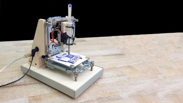
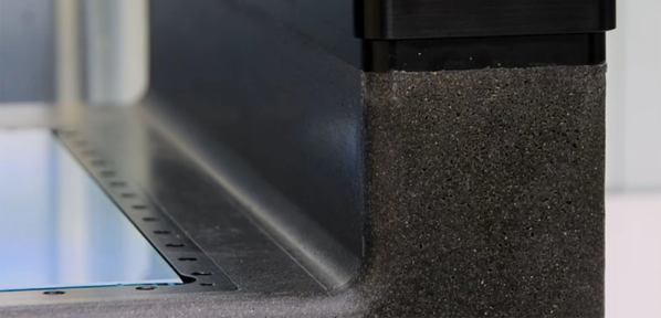
With the correct formula for epoxy granite, [Adam] set up his mold and waxed everything liberally. The internal skeleton, or what the CNC machine will be bolted to, is assembled inside the mold and the epoxy is poured in. The result is fantastic, and an excellent base for a machine that turns metal into chips. You can check out the video below.
Continue reading “Experiments In Creating The Best Epoxy Granite”
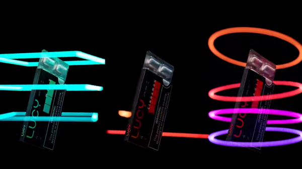
 Light painting is the process of moving a light while taking a long-exposure photograph, which creates a sort of drawing from the path of the light source. It’s been done in one way or another since at least the early-to-mid 1900s, but modern hardware and methods have allowed for all kinds of new spins on this old idea. [Josh Sheldon]