Maybe they weren’t really ever gone but even so Commodore enthusiast [ALWYZ] is here at HOPE X spreading re-awareness of the Commodore 64 and that there is still a community of Commodore fans out there who have been up to some pretty cool projects.
One of those projects is a Quantum Link-esque service called Q-Link Reloaded. Quantum Link was an online service available for Commodore 64 and 128 users that offered electronic mail, online chat, file sharing, online news, and instant messaging. It lasted from the mid-80s to the mid-90’s and later evolved into America Online. In 2005, a group of folks reversed-engineered the original server code and the resultant Q-Link Reloaded lets the Commodore folks once again communicate with each other.
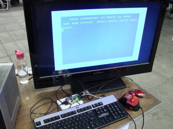
Also on display is a Raspberry Pi running a C64 emulator complete with a controller to GPIO adapter. Hackaday has covered this emulator just a few months ago and it is great to see it working in person.