The flip-flop, in whichever of its several forms you encounter it, is a staple of logic design. Any time that you need to hold onto something, count, or shift bits, out it comes. We expect a flip-flop to be an integrated circuit if we use one, but most of us could knock one together with a couple of transistors.
The circuit is simplicity itself, a pair of incandescent bulbs in series, each in turn in parallel with a momentary action switch and a PTC fuse. On start-up both fuses are conducting, so one or other of them will do its job as a fuse and go high impedance. At that point its bulb will light and the other fuse will remain low impedance so its bulb will stay dark. Press the switch across the lit bulb for a few seconds however, and the circuit resets itself. The other fuse goes high impedance while the first fuse returns to low impedance, and the other bulb lights.
We’re not sure we can see much in the way of practical application for this circuit, but sometimes merely because you can is reason enough. It’s part of our 2025 Component Abuse Challenge, for which you just about still have time to make an entry yourself if you have one.
One of the hardest parts of a project — assuming it makes it that far — is finishing it up in an aesthetically pleasing manner. As they say, the devil is in the details, wearing Prada. Apparently the devil also has an excellent manicure, because [Tamas Feher] has come up with a way to introduce incredibly detailed decals (down to 0.1 mm) in cheap, repeatable fashion, using a technique borrowed from the local nail salon.
The end result can look quite a bit better than the test piece above.
For those who aren’t in to nail art (which, statistically speaking, is likely to be most of you) there is a common “stamping” technique for putting details onto human fingernails. Nail polish is first applied to voids on a stencil-like plate, then picked up by a smooth silicone stamper, which is then pressed against the nail, reproducing the image that was on the stencil. If that’s clear as mud, there’s a quick demo video embedded bellow.
There’s a common industrial technique that works the same way, which is actually where [Tamas] got the idea. For nail salons and at-home use, there are a huge variety of these stencils commercially available for nail art, but that doesn’t mean you’re likely to find what you want for your project’s front panel.
[Tamas] points out that by using a resin printer to produce the stencil plate, any arbitrary text or symbol can be used. Your logo, labels, whatever. By printing flat to the build plate, you can take advantage of the full resolution of the resin printer — even an older 2 K model would more than suffice here, while higher res like the new 16 K models become the definition of overkill. The prints go quick, as they don’t need any structural thickness: just enough to hold together coming off of the plate, plus enough extra to hold your designs at a 0.15 mm inset. That doesn’t seem very thick, but remember that this only has to hold enough nail polish to be picked up by the stamper.
[Tamas] cautions you have to work fast, as the thin layer of nail polish picked up by the stamper can dry in seconds. You’ll want plenty of nail polish remover (or plain acetone) on hand to clean the stamper once you’ve finished, as well as your stencil. [Tamas] cautions you’ll want to clean it immediately if you ever want to use it again. Good to know.
While this is going outside of the nail art kit’s comfort zone, it might not quite be abuse. It is however a very useful technique to add to our ever-growing quiver of how to make front panels. Besides, we don’t specify you have to literally make components suffer; we just want to see what wild and wonderful substitutions and improvisations you all come up with.
Conductive filament is a meltable resistor, which, if one squints hard enough, is basically a fuse.
In theory a 3D printed fuse works the same as a normal one: excessive current draw will cause the conductive plastic to briefly become a heater, causing it to self-destruct and break the electrical connection. There’s a risk of melted plastic and perhaps a nonzero combustion risk, but [JohnsonFarms.us] is less interested in whether this is a good idea and more interested in whether it can work at all, and with what degree of predictability and/or regret.
His experiments so far show that printed fuses are essentially meltable resistors with values between 300 Ω and 1250 Ω, depending on shape. What it takes to bring those to roughly 60 °C, where PLA softens, and around 150 °C, where PLA melts, is next on the to-do list.
Whatever conclusions are reached, it is interesting to think of conductive filament as a meltable resistor, and ponder what unusual applications that might allow.
Most conductive filaments have high resistance, but not all. Some, like Electrifi by Multi3D, have extremely low resistance and were used in a project that made 3d-printed logic gates.
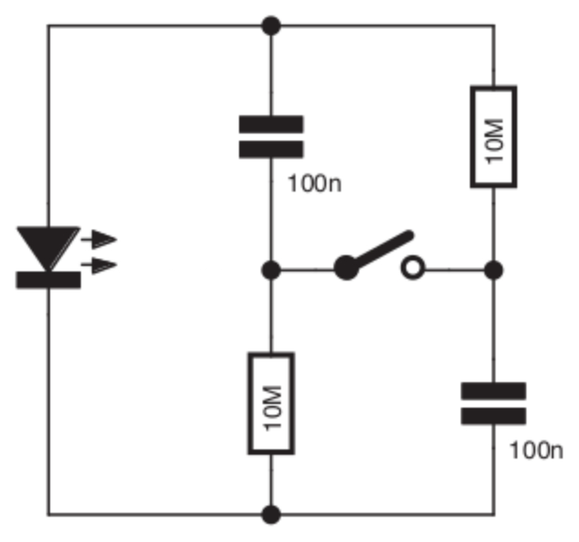
[Tito] entered a Self-Charging LED Flasher into the Component Abuse Challenge. It’s a simple re-build of a design by the unstoppable [Burkhard Kainka], and while [Tito] doesn’t explain its workings in detail, it’s a clever experiment in minimalism, and a bit of a head-scratcher at the same time.
You press a button and an LED flashes. But there is no battery, so how does it work? Maybe the schematic to the right here will help. Or does it confound? Look at it yourself before reading on and see if you can figure out how it works.
Switching power supplies are familiar to Hackaday readers, whether they have a fairly conventional transformer, are a buck, a boost, or a flyback design. There’s nearly always an inductor involved, whose rapid change in magnetic flux is harnessed to do voltage magic. [Craig D] has made a switching voltage booster that doesn’t use an inductor, instead it’s using a length of conductor, and no, it’s not using the inductance of that conductor as a store of magnetic flux.
Instead it’s making clever use of reflected short pulses in a transmission line for its operation. Electronics students learn all about this in an experiment in which they fire pulses down a length of coax cable and observe their reflections on an oscilloscope, and his circuit is very similar but with careful selection of pulse timing. The idea is that instead of reflected pulses canceling out, they arrive back at the start of the conductor just in time to meet a pulse transition. This causes them to add rather than subtract, and the resulting higher voltage pulse sets off down the conductor again to repeat the process. We can understand the description, but this is evidently one to sit down at the bench and experiment with to fully get to grips with.
The function of an LED is to emit light when the device is forward biased within its operating range, and it’s known by most people that an LED can also operate as a photodiode. Perhaps some readers are also aware that a reverse biased LED also has a significant capacitance, to the extent that they can be used in some RF circuits in the place of a varicap diode. But how do those two unintentional properties of an LED collide? As it turns out, an LED can also behave as a light dependent capacitor. [Bornach] has done just that, and created a light dependent sawtooth oscillator.
The idea is simple enough, there is a capacitance between the two sides of the depletion zone in a reverse biased diode, and since an LED is designed such that its junction is exposed to the external light, any photons which hit it will change the charge on the junction. Since the size of the depletion zone and thus the capacitance is dependent on the voltage and thus the charge, incoming light can thus change the capacitance.
The circuit is a straightforward enough sawtooth oscillator using an op-amp with a diode in its feedback loop, but where we might expect to find a capacitor to ground on the input, we find our reverse biased LED. The video below the break shows it in operation, and it certainly works. There’s an interesting point here in that and LED in this mode is suggested as an alternative to a cadmium sulphide LDR, and it’s certainly quicker responding. We feel duty bound to remind readers that using the LED as a photodiode instead is likely to be a bit simpler.
This project is part of the Hackaday Component Abuse Challenge, in which competitors take humble parts and push them into applications they were never intended for. You still have time to submit your own work, so give it a go!
When we think of a motor controller it’s usual to imagine power electronics, and a consequent dent in the wallet when it’s time to order the parts. But that doesn’t always have to be the case, as it turns out that there are many ways to control a motor. [Bram] did it with a surprising part, a 74ACT139 dual 4-line demultiplexer.
A motor controller is little more than a set of switches between the supply rails and the motor terminals, and thus how it performs depends on a few factors such as how fast it can be switched, how much current it can pass, and how susceptible it is to any back EMF or other electrical junk produced by the motor.
In this particular application the motor was a tiny component in a BEAM robot, so the unexpected TTL motor controller could handle it. The original hack was done a few decades ago and it appears to have become a popular hack in the BEAM community.
This project is part of the Hackaday Component Abuse Challenge, in which competitors take humble parts and push them into applications they were never intended for. You still have time to submit your own work, so give it a go!