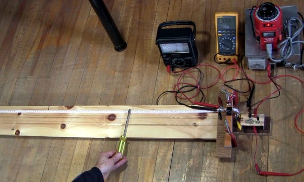
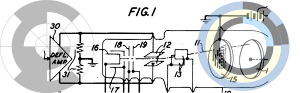
How do you test the oscillator circuit you just made that runs between 200MHz and 380MHz if all you have is a 100MHz oscilloscope, a few multimeters and a DC power supply? One answer is to put away the oscilloscope and use the rest along with a length of wire instead. Form the wire into a Lecher line.
That’s just what I did when I wanted to test my oscillator circuit based around the Mini-Circuits POS-400+ voltage controlled oscillator chip (PDF). I wasn’t going for precision, just verification that the chip works and that my circuit can adjust the frequency. And as you’ll see below, I got a fairly linear graph relating the control voltages to different frequencies.
What follows is a bit about Lecher lines, how I did it, and the results.
It is incredibly interesting how many parts of a computer system are capable of leaking data in ways that is hard to imagine. Part of securing highly sensitive locations involves securing the computers and networks used in those facilities in order to prevent this. These IT security policies and practices have been evolving and tightening through the years, as malicious actors increasingly target vital infrastructure.
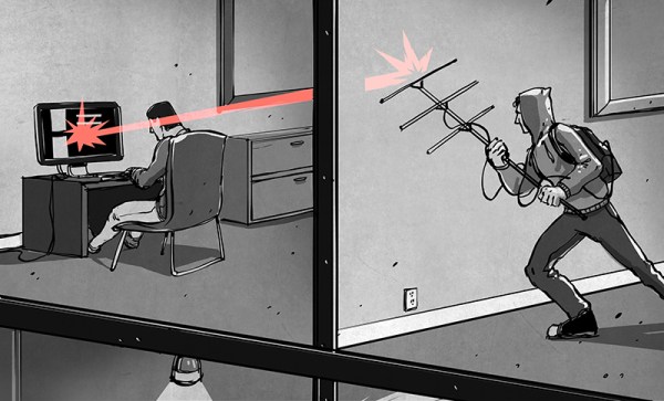
Sometimes, when implementing strong security measures on a vital computer system, a technique called air-gapping is used. Air-gapping is a measure or set of measures to ensure a secure computer is physically isolated from unsecured networks, such as the public Internet or an unsecured local area network. Sometimes it’s just ensuring the computer is off the Internet. But it may mean completely isolating for the computer: removing WiFi cards, cameras, microphones, speakers, CD-ROM drives, USB ports, or whatever can be used to exchange data. In this article I will dive into air-gapped computers, air-gap covert channels, and how attackers might be able to exfiltrate information from such isolated systems.
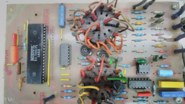
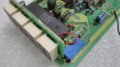
Riffling through my box of old projects, I came upon a project that I had built in the 80’s — an Automotive Multimeter which was published in the Dutch/British Elektor magazine. It could measure low voltage DC, high current DC, resistance, dwell angle, and engine RPM and ran off a single 9V battery. Besides a 555 IC for the dwell and RPM measurement and a couple of CMOS gate chips, the rest of the board is populated by a smattering of passives and a big, 40 pin DIP IC under the 3½ digit LCD display. I dug some more in my box, and came up with another Elektor project from back then — a True RMS digital Wattmeter with a 3½ digit LCD display that could measure up to 2kW. It had the same chip too. Some more digging, and I found a digital panel meter. This had a 7 segment LED display, but the chip was again from the same family.
ICL7107 LED version
Look under the hood of any device with a 3½ or 4½ digit, 7 segment, LCD or LED from the ’80’s or ’90’s and you will likely spot this 40-pin DIP with the Intersil logo (although it was later also manufactured by many other fabs; Harris and Maxim among others). The chip doing all the heavy-lifting was likely to be the ICL7106 or ICL7107. These devices were described as high performance, low power, 3½ digit A/D converters containing seven segment decoders, display drivers, voltage reference and clock. In short, everything you needed to take a DC analog signal and display it. Over time, a whole series of devices were spawned:
There were many similar devices available, but the ICL71xx series was by far one of the most popular, due to its easy of use, low parts count and single chip implementation. Here are several parts (linking to PDF datasheets) to illustrate my point: the TC14433/A needed several peripheral devices, ES5107 (a clone of a clone — read below), CA3162 (which has BCD output, and needs the CA3161 or similar to interface to a display), or the AD2020 (which too needed a lot of support circuitry).
The ICL71xx was the go-to device for a reason. Let’s take a look at the engineering and business behind this fascinating chip.
There are certain design guidelines for PCBs that don’t make a lot of sense, and practices that seem excessive and unnecessary. Often these are motivated by the black magic that is RF transmission. This is either an unfortunate and unintended consequence of electronic circuits, or a magical and useful feature of them, and a lot of design time goes into reducing or removing these effects or tuning them.
You’re wondering how important this is for your projects and whether you should worry about unintentional radiated emissions. On the Baddeley scale of importance:
Pffffft – You’re building a one-off project that uses battery power and a single microcontroller with a few GPIO. Basically all your Arduino projects and around-the-house fun.
Meh – You’re building a one-off that plugs into a wall or has an intentional radio on board — a run-of-the-mill IoT thingamajig. Or you’re selling a product that is battery powered but doesn’t intentionally transmit anything.
Yeeeaaaaahhhhhhh – You’re selling a product that is wall powered.
YES – You’re selling a product that is an intentional transmitter, or has a lot of fast signals, or is manufactured in large volumes.
Some years back, a museum asked me to help them with an exhibit a contractor had built for them. It was a wheel like the one on Wheel of Fortune, but smaller and mounted on the wall instead of the floor. You would spin the wheel, it would stop on some item, and a computer would play a short video about the item. Physically and mechanically, it was a beautifully built exhibit. The electronics, though, left something to be desired.
In principle, this is pretty simple computer task. Measure the position of the wheel, and when it stops moving, play a video based on the position. The problem was the folks who created the artistic mechanics didn’t think hard about the electronics behind it. Sometimes–but not often–the wheel would play the wrong video. Sometimes it wouldn’t play at all.
The Prime Suspect
My immediate suspicion turned out to be correct. I took the wheel off its mount to discover copper foil tape on the back of it. Each pie wedge had foil in different areas and there were two brushes in each area. When the wheel stopped, two of the brushes would be shorted together and the rest were open. The way they detected that was bizarre, but that wasn’t the problem. (It involved a cannibalized PS/2 keyboard.) Continue reading “Fifty Shades Of Gray Code”→
The start of World War II threw quantum theory research into disarray. Many of the European physicists left Europe all together, and research moved across the ocean to the shores of the United States. The advent of the atomic bomb thrust American physicists into the spotlight, and physicists began to meet on Shelter Island to discuss the future of quantum theory. By this time one thing was certain: the Copenhagen interpretation of quantum theory had triumphed and challenges to it had mostly died off.
This allowed physicists to focus on a different kind of problem. At this point in time quantum theory was not able to deal with transitional states of particles when they are created and destroyed. It was well known that when an electron came into contact with a positron, the two particles were destroyed and formed at least two photons with a very high energy, known as gamma rays. On the flip side, gamma ray photons could spontaneously turn into positron-electron pairs.
No one could explain why this occurred. It had become obvious to the physicists of the day that a quantum version of Maxwell’s electromagnetic field theory was needed to explain the phenomenon. This would eventually give rise to QED, short for quantum electrodynamics. This is a severely condensed story of how that happened.
Recently, [Manuel] did a post on making logic gates out of anything. He mentioned a site about relay logic. While it is true that you can build logic gates using switch logic (that is, two switches in series are an AND gate and two in parallel are an OR gate), it isn’t the only way. If you are wiring a large circuit, there’s some benefit to having regular modules. A lot of computers based on discrete switching elements worked this way: you had a PCB that contained some number of a basic gate (say, a two input NAND gate) and then the logic was all in how you wired them together. And in this context, the SPDT relay was used as a two input multiplexer (or mux).
In case you think the relay should be relegated to the historical curiosity bin, you should know there are still applications where they are the best tool for the job. If you’re not convinced by normal macroscopic relays, there is some work going on to make microscopic relays in ICs. And even if they don’t use relays to do it, some FPGAs use mux-based logic inside. So it’s worth your time to dig into the past and see how simply switching between two connections can make a computer.
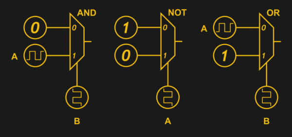
Mux Mania
How do you go from a two input mux to an arbitrary logic gate? Simple, if you paid attention to the banner image. (Or try it interactive). The mux symbols show the inputs to the left, the output to the right and the select input at the bottom. If the select is zero, the “0” input becomes the output. If the select is one, the “1” input routes to the output.