In the annals of ambitious engineering projects, few have captured the imagination and courted controversy quite like Gerald Bull’s Supergun. Bull, a Canadian artillery expert, envisioned a gun that could shoot payloads directly into orbit. In time, his ambition led him down a path that ended in both tragedy and unfinished business.
Depending on who you talk to, the Supergun was either a new and innovative space technology, or a weapon of war so dangerous, it couldn’t be allowed to exist. Ultimately, the powers that be intervened to ensure we would never find out either way.
In order to understand something, it helps to observe it up close and study its inner workings. This is no less true for the brain, whether it is the brain of a mouse, that of a whale, or the squishy brain inside our own skulls. It defines after all us as a person; containing our personality and all our desires and dreams. There are also many injuries, disorders and illnesses that affect the brain, many of which we understand as poorly as the basics of how memories are stored and thoughts are formed. Much of this is due to how complicated the brain is to study in a controlled fashion.
Recently a breakthrough was made in the form of a detailed map of the cells and synapses in a segment of a human brain sample. This collaboration between Harvard and Google resulted in the most detailed look at human brain tissue so far, contained in a mere 1.4 petabytes of data. Far from a full brain map, this particular effort involved only a cubic millimeter of the human temporal cortex, containing 57,000 cells, 230 millimeters of blood vessels and 150 million synapses.
Ultimately the goal is to create a full map of a human brain like this, with each synapse and other structures detailed. If we can pull it off, the implications could be mind-bending.
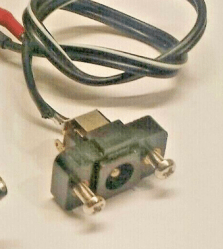
Today is another board from a friend, [treble], who wants to convert a Yaesu FRG7700 radio to USB-C PD power. It’s yet another review that I’ve done privately, and then realized I’ve made more than enough changes to it, to the point that others could learn from this review quite a bit. With our hacker’s consent, I’m now sharing these things with you all, so that we can improve our boards further and further.
This board’s idea is thought-out and executed well – it replaces a bespoke barrel jack assembly, and is mechanically designed to fit the screw holes and the free space inside the chassis. For USB-PD, it uses a CH32V003 coupled with FUSB302 – I definitely did help pick the latter! For mechanical reasons, this board is split into two parts – one has the USB-C port, whereas the other has the MCU and the PD PHY.
In short, this board is a PD trigger. Unlike the usual PD triggers, however, this one is fully configurable, since it has a 32-bit MCU with good software support, plus, the PD PHY is also well known and easily controllable. So, if you want special behavior like charger-power-dependent profile selection for powering a static resistance load, you can implement it easily – or, say, you can do PPS for variable voltage or even lithium ion battery charging! With a bit of extra code, you could even do EPR (28 V = 140 W power) with this board, instantly making it into a pretty advanced PD trigger, beyond the ones available on the market.
Also, the board has some PCB art, and a very handy filter to get some of the USB-C charger noise out. Let’s take a look at all of these!
To those who have kept tabs on nuclear fusion research the past decades beyond the articles and soundbites in news outlets, it’s probably clear just how much progress has been made, and how many challenges still remain. Yet since not that many people are into plasma physics, every measure of progress, such as most recently by the South Korean KSTAR (Korea Superconducting Tokamak Advanced Research) tokamak, is met generally by dismissive statements about nuclear fusion always being a certain number of decades away. Looking beyond this in coverage such as the article by Science Alert about this achievement by KSTAR we can however see quite a few of these remaining challenges being touched upon.
Recently KSTAR managed to generate 100 million degrees C plasma and maintain this for 48 seconds, a significant boost over its previous record from 2021 of 30 seconds, partially due to the new divertors that were installed. These divertors are essential for removing impurities from the plasma, yet much like the inner wall of the reactor vessel, these plasma-facing materials (PFM) bear the brunt of the super-hot plasma and any plasma instabilities, as well as the constant neutron flux from the fusion products. KSTAR now features tungsten divertors, which has become a popular material choice for this component.
Researching the optimal PFMs, as well as plasma containment modes and methods to suppress plasma instabilities are just some of the challenges that form the road still ahead before commercial fusion can commence.
Although we usually imagine the conditions in Ancient Egypt to be much like the Egypt of today, back during the Holocene there was significantly more rain as a result of the African Humid Period (AHP). This translated in the river Nile stretching far beyond its current range, with many more branches. This knowledge led a team of researchers to test the hypothesis that the largest cluster of pyramids in the Nile Valley was sited along one of these now long since vanished branches. Their findings are described in an article published in Communications Earth & Environment, by [Eman Ghoneim] and colleagues.
The Ahramat Branch and pyramids along its trajectory. (Credit: Eman Ghoneim et al., 2024)
The CliffsNotes version can be found in the accompanying press release by the University of North Carolina Wilmington. Effectively, the researchers postulated that a branch of the Nile existed along these grouping of pyramids, with their accompanying temples originally positioned alongside this branch. The trick was to prove that a river branch once existed in that area many thousands of years ago.
What complicates this is that the main course of the Nile has shifted over the centuries, and anthropogenic activity has obscured much what remained, making life for researchers exceedingly difficult. Ultimately a combination of soil core samples, geophysical evidence, and remote sensing (e.g. satellite imagery) helped to cement the evidence for the existence what they termed the Ahramat Nile Branch, with ‘ahramat’ meaning ‘pyramids’ in Arabic.
Synthetic Aperture Radar (SAR) and high-resolution radar elevation data provided evidence for the Nile once having traveled right past this string of pyramids, also identifying the modern Bahr el-Libeini canal as one of the last remnants of the Ahramat Branch before the river’s course across the floodplain shifted towards the East, probably due to tectonic activity. Further research using Ground Penetrating Radar (GPR) and Electromagnetic Tomography (EMT) along a 1.2 km section of the suspected former riverbed gave clear indications of a well-preserved river channel, with the expected silt and sediments.
Soil cores to a depth of 20 and 13 meters further confirmed this, showing not only the sediment, but also freshwater mussel shells at 6 meter depth. Shallow groundwater was indicated at these core sites, meaning that even today subsurface water still flows through this part of the floodplain.
These findings not only align with the string of pyramids and their causeways that would have provided direct access to the water’s edge, but also provided hints for a further discovery regarding the Bent Pyramid — as it’s commonly known — which is located deep inside the desert today. Although located far from the floodplain by about a kilometer, its approximately 700 meters long causeway terminates at what would have been a now extinct channel: the Dahshur Inlet, which might also have served the Red Pyramid and others, although evidence for this is shakier.
Altogether, these findings further illustrate an Ancient Egypt where the Old Kingdom was followed by a period of severe changes, with increasing drought caused by the end of the AHP, an eastwardly migrating floodplain and decreased flow in the Nile from its tributaries. By the time that European explorers laid eyes on the ancient wonders of the Ancient Egyptian pyramids, the civilization that had birthed them was no more, nor was the green and relatively lush environment that had once surrounded it.
We take for granted that electrical power standards are generally unified across countries and territories. Europe for instance has a standard at 230 volts AC, with a wide enough voltage acceptance band to accommodate places still running at 220 or 240 volts. Even the sockets maintain a level of compatibility across territories, with a few notable exceptions.
It was not always this way though, and to illustrate this we have [Sam], who’s provided us with a potted history of mains power in Italy. The complex twists and turns of power delivery in that country reflect the diversity of the power industry in the late 19th and early 20th century as the technology spread across the continent.
Starting with a table showing the impressive range of voltages found across the country from differing power countries, it delves into the taxation of power in Italy which led to two entirely different plug standards, and their 110/220 volt system. Nationalization may have ironed out some of the kinks and unified 220 volts across the country, but the two plugs remain.
Altogether it’s a fascinating read, and one which brings to mind that where this is being written you could still find a few years ago some houses with three sizes of the archaic British round-pin socket. Interested in the diversity of plugs? We have a link for that.
Most of the Hackaday community would never wire a power supply to a circuit without knowing the expected voltage and the required current. But our mechanical design is often more bodged. We meet folks who carefully budget power to their microcontroller, sensors, and so on, but never measure the forces involved in their mechanical designs. Then they’re surprised when the motor they chose isn’t big enough for the weight of their robot.
An obstacle to being more numbers oriented is lack of basic data about the system. So, here are some simple tools for measuring dynamic properties of small mechanisms; distances, forces, velocities, accelerations, torques, and other things you haven’t thought about since college physics. If you don’t have these in your toolkit, how do you measure?


 This board’s idea is thought-out and executed well – it replaces a bespoke barrel jack assembly, and is mechanically designed to fit the screw holes and the free space inside the chassis. For USB-PD, it uses a CH32V003 coupled with FUSB302 – I definitely