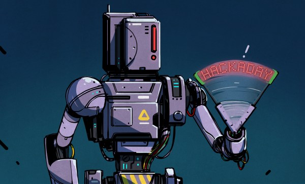
Have you ever had one of those moments, when you’re rummaging through your spare parts heap, and have a rather bizarre project idea that you can’t quite get out of your head? You know, the ones that have no clear use, but simply demand to be born, of glass and steel and silicon?
This time, the stubborn idea in question was sort of like a solar-rechargeable LED throwie, but instead of a blinking light, it has a fully cloud-accessible embedded Linux server in the form of a Raspberry Pi 3 Model B+. Your choice of embedded Linux board should work — I just happen to have a lot of these due to a shipping error.
There were two main challenges here: First, it would have to combine the smallest practical combination of solar panel, power supply, and Li-ion cell that could run the Raspberry Pi. Second, we’ll need to remotely activate and access the Pi regardless of where it is, as well as be able to connect it to WiFi without direct physical access. In this article we’ll be dealing with the first set of problems — stay tuned for the rest.
Continue reading “The Linux Throwie: Powering A Linux Server With A 0.3W Solar Panel”
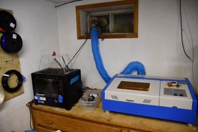 Over the last decade or so things have changed. China got involved, and suddenly there were cheap lasers on the market. Currently, there are several low-cost laser models available in various power levels. The most popular is the smallest – a 40-watt model, dubbed the K40. There are numerous manufacturers and there have been many versions over the years. They all look about the same though: A blue sheet metal box with the laser tube mounted along the back. The cutting compartment is on the left and the electronics are on the right. Earlier versions came with Moshidraw software and a parallel interface.