As an Apple user, I’ve become somewhat disillusioned over the past few years. Maybe it’s the spirit of Steve Jobs slowly vanishing from the company, or that Apple seems to care more about keeping up with expensive trends lately rather than setting them, or the nagging notion Apple doesn’t have my best interests as a user in mind.
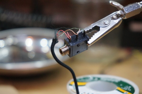
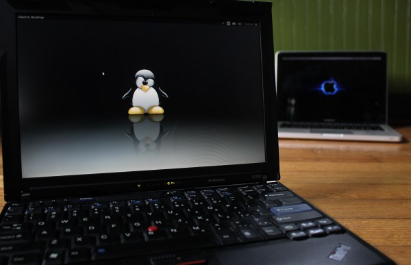
Whatever it is, I was passively on the hunt for a new laptop with the pipe dream that one day I could junk my Apple for something even better. One that could run a *nix operating system of some sort, be made with quality hardware, and not concern me over privacy issues. I didn’t think that those qualities existed in a laptop at all, and that my 2012 MacBook Pro was the “lesser of evils” that I might as well keep using. But then, we published a ThinkPad think piece that had two words in it that led me on a weeks-long journey to the brand-new, eight-year-old laptop I’m currently working from. Those two words: “install libreboot”.
Continue reading “Harrowing Story Of Installing Libreboot On ThinkPad”