You Are Go For FPGA!

Reconfigure.io is accepting beta applications for its environment to configure FPGAs using Go. Yes, Go is a programming language, but the software converts code into FPGA constructs, so you don’t need Verilog or VHDL. Since Go supports concurrent routines and channels for synchronization and communications, the parallel nature of the FPGA should fit well.

According to the project’s website, the tool also allows you to reconfigure the FPGA on the fly using a cloud-based build and deploy system. There isn’t much detail yet, unless you get accepted for the alpha. They claim they’ll give priority to the most interesting use cases, so pitching your blinking LED project probably isn’t going to cut it. There is a bit more detail, however, on their GitHub site.

Continue reading “You Are Go For FPGA!”

Quality Assurance Through FPGA

[Claire Chen] and [Mark Zhao], students in [Bruce Land]’s ECE5760 class at Cornell, created a project aimed at the manufacturing sector: quality-checking manufactured products automatically by visually scanning a bunch of them and processing the pixels one at a time. Ordinarily, the time when the widget comes off the line is when you have to bring in actual people to inspect. This project uses morphological image processing to like dilation and erosion to look for flaws.

[Claire] and [Mark] created a simulated manufacturing line with a servo-driven belt that brings a series of Spree candies into the range of a camera, which scans them. The SoC with a Cyclone V FPGA and ARM Cortex-9 then processes the raw images to establish the object’s color, while running it through a couple of algorithms to look for defects. The FPGA tracks how many Sprees that have passed by as well as their color, maintaining a 99% success rate with a rate of 5-10 frames per second. The FPGA also looks at each blob of color as a collection of pixels, establishing connectivity to help to distinguish multiple Sprees touching each other.

Also be sure to check out [Claire] and [Mark]’s bike sonar project from a previous semester.

Continue reading “Quality Assurance Through FPGA”

Run From The Sound Of Footsteps In Blind Game Of Tag

The human auditory system is a complex and wonderful thing. One of its most useful features is the ability to estimate the range and direction of sound sources – think of the way people instinctively turn when hearing a sudden loud noise. A team of students have leveraged this innate ability to produce a game of tag based around nothing but sound.

The game runs on two FPGAs, which handle the processing and communication required. The chaser is given a screen upon which they can see their own location and that of their prey. The target has no vision at all, and must rely on the sounds in their stereo headphones to detect the location of the chaser and evade them as long as possible.

The project documentation goes into great detail about the specifics of the implementation. The game relies on the use of the Head Related Transfer Function – a function related to how the ear picks up sounds relative to their position. This allows the FPGA to simulate the chaser’s footsteps, and feed the audio to the target who perceives the chaser’s position purely by sound.

It’s a great example of a gameplay mechanic that we’d love to see developed further. The concept of trying to find one’s way around by hearing alone is one which we think holds a lot of promise.

With plenty of processing power under the hood, FPGAs are a great choice for complex audio projects. A great project to try might be decoding MP3s.


An Education On SoC Using Verilog

[Bruce Land] is one of those rare individuals who has his own Hackaday tag. He and his students at Cornell have produced many projects over the years that have appeared on these pages, lately with FPGA-related projects. If you only know [Land] from projects, you are missing out. He posts lectures from many of his classes and recently added a series of new lectures about developing with a DE1 System on Chip (SoC) using an Altera Cyclone FPGA using Verilog. You can catch the ten lectures on YouTube.

The class material is different for 2017, so the content is fresh and relevant. The DE1-SOC has a dual ARM processor and boots Linux from an SD card. There are several labs and quite a bit of background material. The first lab involves driving a VGA monitor. Another is a hardware solver for ordinary differential equations.

Continue reading “An Education On SoC Using Verilog”

Logic Analyzer On Chips

The Internet is full of low-speed logic analyzer designs that use a CPU. There are also quite a few FPGA-based designs. Both have advantages and disadvantages. FPGAs are fast and can handle lots of data at once. But CPUs often have more memory and it is simpler to perform I/O back to, say, a host computer. [Mohammad] sidestepped the choice. He built a logic analyzer that resides partly on an FPGA and partly on an ARM processor.

In fact, his rationale was to replace built-in FPGA logic analyzers like Chipscope and SignalTap. These are made to coexist with your FPGA design, but [Mohammad] found they had limitations. They also eat up die space you might want for your own design, so by necessity, they probably don’t have much memory.

The system can capture and display 32-bit signals on a 640×480 VGA monitor in real-time. The system also has a USB mouse interface which is used to zoom and scroll the display. You can see a video of the thing in operation, below.

Continue reading “Logic Analyzer On Chips”

Simulating The Learn-by-Fixing CPU

Last time I looked at a simple 16-bit RISC processor aimed at students. It needed a little help on documentation and had a missing file, but I managed to get it to simulate using a free online tool called EDA Playground. This time, I’ll take you through the code details and how to run the simulation.

You’ll want to refer to the previous post if you didn’t read it already. The diagrams and tables give a high-level overview that will help you understand the files discussed in this post.

If you wanted to actually program this on a real FPGA, you’d have a little work to do. The memory and register initialization is done in a way that works fine for simulation, but wouldn’t work on a real FPGA. Anyway, let’s get started!

Continue reading “Simulating The Learn-by-Fixing CPU”

A Full Stack GPS Receiver

The usual way of adding GPS capabilities to a project is grabbing an off-the-shelf GPS module, plugging it into a UART, and reading the stream of NMEA sentences coming out of a serial port. Depending on how much you spend on a GPS module, this is fine: the best modules out there start up quickly, and a lot of them recognize the logical AND in ITAR regulations.

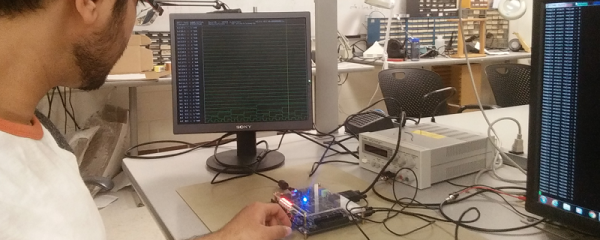
For [Mike], grabbing an off-the-shelf module is out of the question. He’s building his own GPS receiver from the ground up using a bit of hardware and FPGA hacking. Already he’s getting good results, and he doesn’t have to futz around with those messy, ‘don’t build ballistic missiles’ laws.

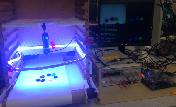
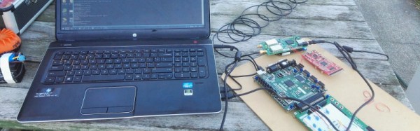
The hardware for this build includes a Kiwi SDR ‘cape’ for the BeagleBone and a Digilent Nexus-2 FPGA board. The SDR board captures raw 1-bit samples taken at 16.268 MHz, and requires a full minute’s worth of data to be captured. That’s at least 120 Megabytes of data for the FPGA to sort through.

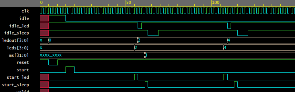
The software for this project first acquires the GPS signal by finding the approximate frequency and phase. The software then locks on to the carrier, figures out the phase, and receives the 50bps ‘NAV’ message that’s required to find a position solution for the antenna’s location. The first version of this software was exceptionally slow, taking over 6 hours to process 200 seconds of data. Now, [Mike] has improved the channel tracking code and made it 300 times faster. That’s real-time processing of GPS data, using commodity off-the-shelf hardware. All the software is available on the Gits, making this a project that can very easily be replicated by anyone. We would expect the US State Department or DOD to pay [Mike] a visit shortly.

Of course, this isn’t the first time someone has built a GPS receiver from scratch. A few years ago, less than 1-meter accuracy was possible with an FPGA and a homebrew RF board.