On the whole, hackers aren’t overly fond of other people telling them what they can and cannot do with the hardware or software they’ve purchased. Unfortunately, it’s becoming more and more difficult to avoid DRM and other Draconian rules and limitations as time goes on. Digital “eBooks” and the devices that are used to view them are often the subject of such scrutiny, which is why [Joey Castillo] has made it his mission to develop a open hardware eReader that truly belongs to the user.
[Joey] has been working on what he calls the “The Open Book Project” for a few months now, and he’s just recently announced that the first reader has been successfully assembled and powered up. As is usually the case, a few hardware issues were identified with this initial prototype. But it sounds like the device was largely functional, and only a few relatively minor tweaks to the board layout and components should be necessary before the hardware is ready for the masses.
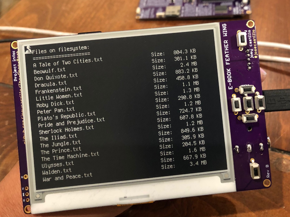
If you’re feeling a bit of déjà vu seeing this, don’t worry. The Open Book Project has taken a somewhat circuitous path to get to this first prototype, and [Joey] had previously developed and built the “eBook Feather Wing”. While they look very similar, that earlier incarnation required an Adafruit Feather to operate and was used to help refine the firmware and design concepts that would go into the final hardware.
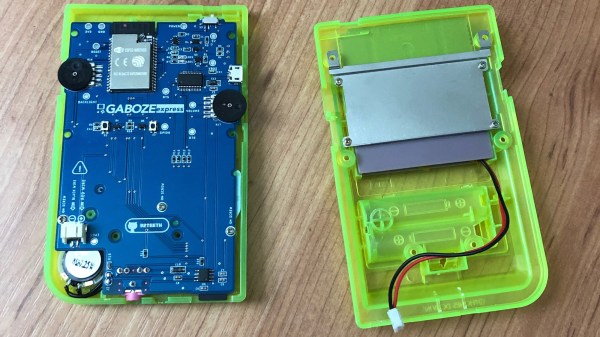
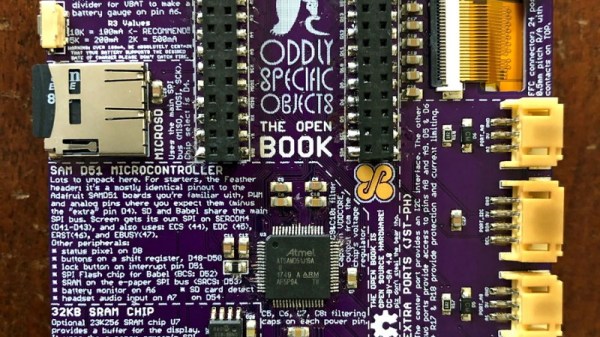
The Open Book is powered by a ATSAMD51N19A processor with a GD25Q16 2MB flash chip to hold the CircuitPython code, and a microSD slot to store the actual book files. It also features support for audio output via a standard 3.5 mm headset jack, an RGB status LED, and expansion ports that tap into the I2C interface for adding whatever other hardware you can dream up.
One of the most interesting aspects of this Creative Commons licensed reader is the extensive self documentation [Joey] has included on the silkscreen. Every major component on the back of the PCB has a small description of its purpose and in some cases even a breakdown of the pin assignments. The idea being that it not only makes the device easier to assemble and debug, but that it can also explain to the curious user what everything on the board does and why it’s necessary. It’s a concept that makes perfect sense given the goals of the Open Book Project, and something that we frankly would love to see more of.
[Marc Juul] presented his work on a FOSS operating system for older-model Kindles at HOPE XII as a way to avoid Orwellian monitoring of the user’s reading habits, so it’s interesting to see somebody take this idea to the next level with completely libre reader hardware. Unfortunately none of this addresses the limited availability of DRM-free eBooks, but one step at a time.


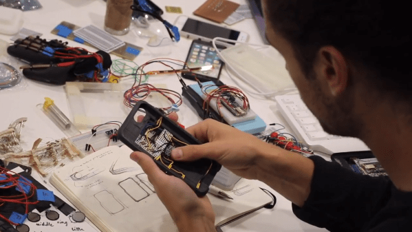
 Smartphones and other modern computing devices are wonderful things, but for those with disabilities interacting with them isn’t always easy. In trying to improve accessibility, [Dougie Mann] created