From the blog of [telmomoya] we found his latest project: a hardware based multicore solution for a ZX Spectrum Emulator. It’s not the first time we feature one of his builds, last year we was working on a ARM Dual-Core Commodore C64. Luckily for Speccy fans, it seems a ZX Spectrum project was just unavoidable.
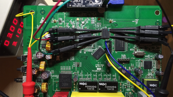
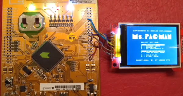
At its heart is the EduCIAA NXP Board, a Dual Core (M4 & M0) 32-bit microcontroller, based on the NXP LPC4337. It’s an Argentinan-designed microcontroller board, born from an Argentinian academic and industry joint venture. [telmomoya] took advantage of the multicore architecture by running the ZX Spectrum emulator on M4 core and generating the VGA signals with M0 core. This guarantees that the VGA generation, which is rather time-sensitive, remains isolated from emulation and any task running on other core. The VGA sync is via polling and using DMA GPIO the RGB signals can be up to 256 colors. To store the 48 kb VGA frames one AHB32 and one AHB16 memory IC are used.
On the software side, [telmomoya] adopted Aspectrum, a ZX Spectrum Emulator fully written in C, modified to his needs. Overall, the project faced many challenges and issues, like COLOR VGA generation (with GPIO DMA), TFT SPI low fps, Inter Process Communications and bus sharing.
Can you try to name all the games in the demonstration video?