If you mention the word bus, you might think of public transportation or, more likely for us, a way to connect things together. But in the satellite world, the bus is the part of a vehicle that supports the payload but isn’t itself the payload. Typically, that means the electric power system, propulsion, radios, and thermal control, among other systems. If you are designing a CubeSat, you will want to read A Guide to CubeSat Mission and Bus Design by [Frances Zhu].
The Creative Commons-licensed book has twelve chapters, ranging from systems engineering — that is, defining what you want to do — to analyzing structures, handling power, setting up communications, and more. Of particular interest to us was the chapter on command and data handling. The final chapters cover software, system integration, and there’s even a chapter on Ethics.
If you want to build a CubeSat or just want to learn more about how satellites actually work, this is a great read. There are videos and other features, too. If you don’t like reading in your browser, you can download an EPUB, PDF, or MOBI near the top of the page.
It’s fair to say that there are a lot of development board form factors for MCUs, with [Tech Dregs] over on yonder YouTube on the verge of adding another one to the pile, but not before he was having some serious thoughts on the implications of such a decision. Does this world really need another devboard with the ubiquitous 2.54 mm (0.1″) pitch pin headers, all so that it can perhaps be used in the same traditional 2.54 mm pitch breadboards?
The thought that [Tech Dregs] is playing with is to go for something more akin to the system-on-module (SoM) approach that’s reminiscent of the Raspberry Pi compute module form factor. This means using a 1 mm pitch for the headers and castellated edges in case you want use it as an SMT part, while breaking out many more pins of the onboard ESP32 module in far less space.
Obviously, the main advantage of this approach is that much like with compute modules you can leave most of the tedious cheap stuff on a carrier board, while the expensive to manufacture components are on a self-contained module. Meanwhile with the much finer pitch on the SoM contacts it’d straddle the divide between a 2.54 mm breadboard-capable devboard and a fully custom PCB, while making any mistakes on the carrier board much cheaper to redo.
The counterpoint here is of course that something like an ESP32 module is already a module with a finer pitch, but if you need more than just what it offers, or you want to use an STM32 or RP MCU across boards it could make a lot of sense.
Having 1 mm pitch breadboards would honestly also be rather nifty, natch. That said, what are your thoughts on this matter?
A computer does one thing at a time, even if it feels like it’s doing multiple things at once. In reality, it’s just switching between tasks very quickly. But a VLIW (Very Long Instruction Word) computer is different. Today, [Asianometry] tells us about VLIW computing and its history.
Processors have multiple functional units; for example, you might have separate units each for addition, multiplication and division. But because it runs one instruction at a time, these units tend to spend a large amount of time idle. VLIW aims to address this inefficiency by reinventing what an instruction means. Instead of telling the whole processor what to do, a VLIW instruction tells each functional unit what to do at once. Sounds good, right? Well, that was the easy part.
The hard part? How to compile a program for a VLIW computer, that can actually make use of all the functional units at once; after all, the efficiency promise is that the higher activity makes up for larger instruction words to fetch. That is the compiler’s job; VLIW compilers try to reschedule the operations in the program to convert sequential code into more parallel operations then compiled into the titular very long instruction words.
When taking macro photographs, you often need just a tiny bit of controlled motion — so little that it’s tough to pull off by hand. To address this, [Salveo] designed a small open-source macro photography slider featuring an anti-backlash handle.
Macro photography gives you an extremely shallow field of view, sometimes under 1 mm of depth, in which subjects stay in focus. To combat this, it’s common to capture multiple images while sliding the camera forward or backward, then combine them for a much larger depth of field than a single shot provides. [Salveo]’s slider gives fine control over this focus-stacking process, with the knob even marked to show every 1 mm of linear travel.
The slider is built around a 150 mm linear rail, though it could easily be lengthened or shortened to suit your needs. A T8 leadscrew, paired with anti-backlash nuts, translates the knob’s rotation into smooth linear motion. The knob itself uses a custom-designed anti-backlash mechanism to ensure the slider works cleanly in either direction.
You can grab all the 3D-printable files as well as the full bill of materials from the project page. Be sure to check out [Salveo]’s build video below. Thanks [Tim L.] for sending in this awesome open-source slider. Be sure to check out some of the other macro photography projects we’ve covered, too.
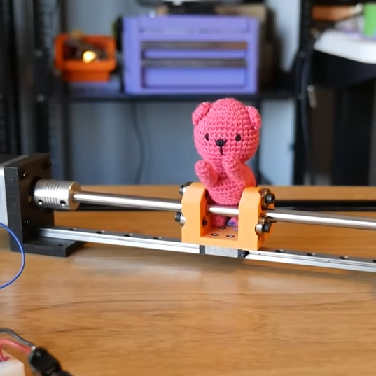
If you’ve never heard of the threadless ball screw, which was invented over sixty years ago, [Angus] of Maker’s Muse has a video demonstrating the whole thing, covering its history and showcasing both its strengths and weaknesses. If you like seeing mechanical assemblies in action, give it a watch.
The device — consisting of little more than a smooth rod and three angled ball bearings — is a way to turn rotational motion into linear motion. Not a single belt, thread, or complex mechanical assembly in sight. While a simple nut on a threaded rod can turn rotation into linear motion, those come with their own issues. The threadless ball screw was one effort at finding a better way.
While it lacks precision, the threadless ball screw nevertheless offers quiet and smooth motion with adjustable tension in a very DIY-friendly design.
Threadless ball screws never really took off, although they were given some consideration for use in 3D printers back in the RepRap days. Today one can purchase quality CNC components without leaving one’s web browser, but back in the early 2000s things like lead screws and ball screws were rather more specialized, less accessible, and more expensive than they are today. RepRap folks had to make their own solutions. But while the threadless ball screw is a very DIY-friendly design, it was ultimately lacking in performance.
The main problem is they’re just not precise enough for anything like CNC work. [Angus] does some back-and-forth tests with a 3D printed unit that shows serious drift after only a few minutes. Now, he knows perfectly well that his 3D-printed test unit is far from ideal, but the rapidity at which it drifted was still a surprise. Making a carriage with two threadless ball screws — one at each end — performed a lot better, but was ultimately still flawed.
It’s not all bad. There’s zero backlash. They are mechanically simple, remarkably smooth, and utterly quiet. Also, [Angus] discovered that the maximum force this setup can be made to apply is surprisingly significant, and is directly related to the tension on the bearings. That means one can trivially adjust how easily the carriage slips (or doesn’t) just by tightening or loosening the screw holding each bearing.
Sure, they’re not precise. But maybe you don’t need precision. Maybe you just need to move something back and forth in a strong & silent sort of way that can still slip gracefully (and quietly) if something goes awry, like bottoming out an axis. 3D printing makes it pretty easy to whip one up, so maybe there’s still a place for the threadless ball screw.
One of the great things about building electronics today is how affordable SMT components have become — sometimes just fractions of a cent each. That low price often means ordering far more than you need so you’ll have spares on hand the next time a project calls for them. Keeping track of exactly how many of each part you actually have, though, is rarely easy. To solve that problem, [John] built the Dotterboard, an open-source SMT tape counter.
While working on some of his other projects, [John] found himself managing thousands of tiny SMT parts and decided it was time to automate the counting. The Dotterboard takes inspiration from the BeanCounter — a compact, portable SMT tape counter — but expands the design to handle larger components beyond the 8 mm tapes the BeanCounter targets.
The Dotterboard is mostly 3D-printed and uses just a few common hardware parts such as springs and ball bearings. An OLED displays the current count, which comes from an encoder tracking movement and multiplying by the number of components per hole. At the heart sits an RP2040 Zero that needs nothing more than a single USB-C cable for power, unlike the bulky industrial SMT counters that demand AC outlets and desk space.
Be sure to check out all the details of the build on [John]’s website, and grab the files from his GitHub if you want to make your own. Let us know what are some projects you’ve done to save you the headache of doing the same task by hand for hours on end.
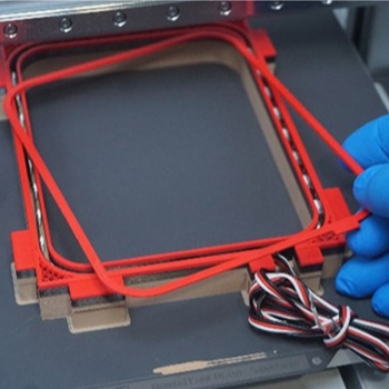
Embedding fasteners or other hardware into 3D prints is a useful technique, but it can bring challenges when applied to large or non-flat objects. The solution? Use a gap-cap.
The gap-cap technique is essentially a 3D printed lid. One pauses a print, inserts hardware, then covers it with a lid before resuming the print. The lid — or gap-cap — does three things. It seals in the part, it fills in empty space left above the component, and it provides a nice flat surface for subsequent layers which makes the whole process much cleaner and more reliable.
This whole technique is a bit reminiscent of the idea of manual supports, except that the inserted piece is intended to be sealed into the print along with the embedded hardware under it.
If you have never inserted anything larger than a nut or small magnet into a 3D print, you may wonder why one needs to bother with a gap-cap at all. The short version is that what works for printing over small bits doesn’t reliably carry over to big, odd-shaped bits.
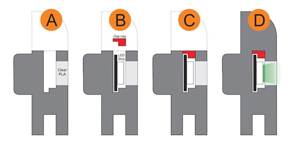
For one thing, filament generally doesn’t like to stick to embedded hardware. As the size of the inserted object increases, especially if it isn’t flat, it increasingly complicates the printer’s ability to seal it in cleanly. Because most nuts are small, even if the printer gets a little messy it probably doesn’t matter much. But what works for small nuts won’t work for something like an LED strip mounted on its side, as shown here.
Cross-section of a print with an embedded LED strip. The print pauses (A), LED strip is inserted and capped with a gap-cap (B, C), then printing resumes and completes (D).
In cases like these a gap-cap is ideal. By pre-printing a form-fitting cap that covers the inserted hardware, one provides a smooth and flat surface that both seals the component in snugly while providing an ideal surface upon which to resume printing.
If needed, a bit of glue can help ensure a gap-cap doesn’t shift and cause trouble when printing resumes, but we can’t help but recall the pause-and-attach technique of embedding printed elements with the help of a LEGO-like connection. Perhaps a gap-cap designed in such a way would avoid needing any kind of adhesive at all.