A friend of ours here at Hackaday has an audacious design in the works that we hope will one day become a prototype that we can feature here. That day may be a little while coming though, because it has somewhere close to a thousand of the smaller SMD components in multiple repeated blocks on a modestly sized board, and his quote from a Chinese board house for assembly is eye-watering. He lacks a pick-and-place machine of his own, and unsurprisingly the idea of doing the job by hand is a little daunting.
We can certainly feel his pain, for in the past we’ve been there. The job described in the linked article had a similar number of components with much more variety and on a much larger board, but still took two experienced engineers all day and into the night to populate. The solder paste had started to spread by the end, morphing from clearly defined blocks to an indistinct mush often covering more than one pad. Our eyes meanwhile were somewhat fatigued by the experience, and it’s not something any sane person would wish to repeat.
Mulling over our friend’s board and comparing it with the experience related above, are we on the edge of what is possible with hand pick-and-place, or should we be working at the next level? Board assembly is a finely judged matter of economics at a commercial level, but when at a one-off personal construction level the option of paying for assembly just isn’t there, is there a practical limit to the scale of the task? Where do you, our readers, draw the line? We’d love to hear your views.
Meanwhile our friend’s audacious project is still shrouded in a bit of secrecy, but we’ll continue to encourage him to show it to the world. It’s not often that you look at a circuit diagram and think “I wish I’d thought of that!”, but from what we’ve seen this fits the category. If he pulls it off then we’ll bring you the result.
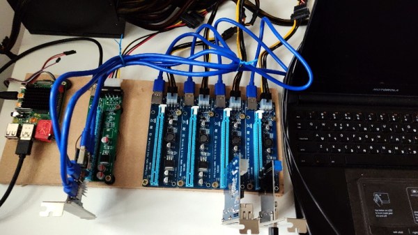
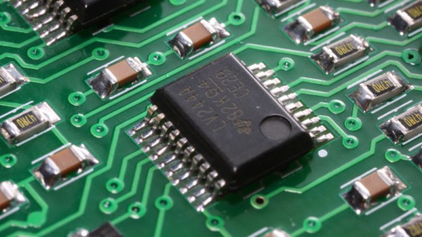
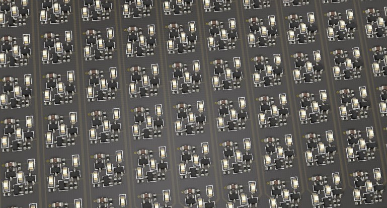
PCB image, Andrew Magill (CC BY 2.0).