Firmware and software are both just code, right? How different could the code that runs Internet-scale distributed web stuff be from the code that runs a tiny microcontroller brain inside a personal hydroponics device? Night and day!
Ruth Grace Wong works in the former world, but moonlights as a manufacturing engineer with some friends. Their product had pre-existing firmware that contained (at least) one bug, and Ruth’s job was to find it. The code in question was written by the Chinese PCB engineer, who knew the electronics intimately but who had no software background, providing Ruth an opportunity to jump head-first into the rawest of raw embedded programming. Spoiler alert: she found the bug and learned a lot about firmware along the way. This talk follows her along the adventure.
“The code is very well documented, in Chinese” but the variable names are insanely non-descriptive. Similarly, while the PCB engineer knows full well what a 24C02 is, if you’re a software geek that might as well be Chinese. As you’d expect, web searches came to the rescue on both fronts.
The bug ended up hiding in a logical flaw in the PWM-setting code inside an interrupt service routine, and it kept the fan from ever coming full on. Once found, it was easily fixed. But getting to the point where you understand the codebase deeply enough to know where to look is four-fifths of the battle. Heck, setting up the toolchain alone can take a day or two.
If you’re a fellow software type, Ruth’s talk (embedded below) will give you a quick glimpse into the outer few layers of the onion that is embedded firmware development, from a familiar viewpoint. Give her quick and value-packed talk a watch! Grizzled hardware veterans will nod along, and maybe even gain a little insight into how our code looks to “them”.
For one reason or another, a lot of us have a bunch of 18650 cells sitting around. Whether they’re for flashlights, our fancy new vape pen, remote controlled toys, or something more obscure, there is a need to charge a bunch of lithium ion cells all at once. This project, by [Daren Schwenke], is the way to do it. It’ll charge ten 18650 cells quickly using a stock ATX power supply and less than twenty bucks in Amazon Prime parts.
The idea began when [Daren] realized his desktop lithium ion charger took between 4-6 hours to fully charge two 18650 cells. With a Mountainboard project, or a big ‘ol electric skateboard waiting in the wings, [Daren] realized there had to be a better solution to charging a bunch of 18650 cells. There is, and it’s those twenty bucks at Amazon and a few 3D printed parts.
The relevant parts are just a ten-pack of 18650 cell holders (with PC pins) and a ten-pack of 5V, 1A charging modules (non-referral Amazon link, support truly independent journalism) meant to be the brains of a small USB power bank. These parts were wired up to the 5V rail of a discarded ATX power supply (free, because you can scavenge these anywhere, and everything was wrapped up with a neat little 3D printed mount.
Is this the safest way to charge lithium ion cells? No, because you can build a similar project with bailing wire. There is no reverse polarity protection, and if there’s one thing you never want to do, it’s reverse the polarity. This is, however, a very effective and very cheap solution to charging a bunch of batteries. It does what it says it’ll do, nothing more.
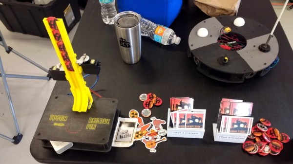
Regular readers of Hackaday have certainly seen the work of [Jeremy Cook] at this point. Whether you remember him from his time as a writer for this fine online publication, or recognize the name from one of his impressive builds over the last few years, he’s a bona fide celebrity around these parts. In fact, he’s so mobbed with fans at events that he’s been forced to employ a robotic companion to handle distributing his personalized buttons for his own safety.
Alright, that might be something of a stretch. But [Jeremy] figured it couldn’t hurt to have an interesting piece of hardware handing out his swag at the recent Palm Bay Mini Maker Faire. Anyone can just put some stickers and buttons in a bowl on a table, but that’s hardly the hacker way. In the video after the break, he walks viewers through the design and construction of this fun gadget, which takes a couple unexpected turns and has contains more than a few useful tips which are worth the cost of admission alone.
Outwardly the 3D printed design is simple enough, and reminds us of those track kits for Matchbox cars. As you might expect, getting the buttons to slide down a printed track was easy enough. Especially when [Jeremy] filed the inside smooth to really get them moving. But the goal was to have a single button get dispensed each time the device was triggered, but that ended up being easier said than done.
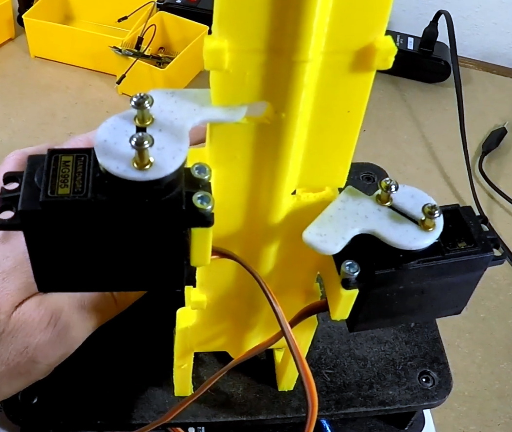
The first attempt used magnets actuated by two servos, one to drop the button and the other to hold up the ones queued above it. This worked fine…at first. But [Jeremy] eventually found that as he stacked more buttons up in the track, the magnets weren’t strong enough to hold them back and they started “leaking”. This is an excellent example of how a system can work perfectly during initial testing, but break down once it hits the real world.
In this case, the solution ended up being relatively simple. [Jeremy] kept the two servos controlled by an Arduino and a capacitive sensor, but replaced the magnets with physical levers. The principle is the same, but now the system is strong enough to hold back the combined weight of the buttons in the chute. It did require him to cut into the track after it had already been assembled, but we can’t blame him for not wanting to start over.
We all know CERN as that cool place where physicists play with massive, superconducting rings to smash atoms and subatomic particles to uncover secrets of matter in the Universe. To achieve this aim, they need to do a ton of research in other areas, such as development of special particle detectors.
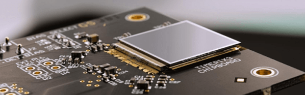
While such developments are essential to the core research needs of the Centre, they also lead to spinoff applications for the benefit of society at large. One such outcome has been the Medipix Collaborations – a family of read-out chips for particle imaging and detection that can count single photons, allowing X-rays and gamma rays to be converted to electrical signals. It may not be possible for us hackers to get our hands on these esoteric sensors, but these devices are pretty interesting and deserve a closer look. Medipix sensors work like a camera, detecting and counting each individual particle hitting the pixels when its electronic shutter is open. This enables high-resolution, high-contrast, noise hit free images – making it unique for imaging applications.
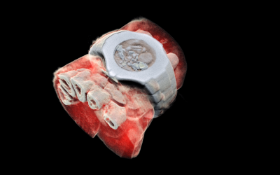
Some months back, CERN announced the first 3D color X-ray of a human made possible using the Medipix devices. The result is a high-resolution, 3D, color image of not just living structures like bones, muscular tissues and vessels, but metal objects too like the wrist watch, seen in the accompanying photograph. The Medipix sensors have been in development since the 1990’s and are presently in their 4th “generation”. Each chip consists of a top semiconducting sensor array, made from gallium arsenide or cadmium telluride. The charge collected by each pixel is transported to the CMOS ASIC electronics via “bump bonds”. The integration is vertical, with each sensing pixel connected via the bump bond to an analog section followed by a digital processing layer. Earlier versions were limited, by technology, in their tiling ability for creating larger matrices of multiple sensors. They could be abutted on three sides only, with the fourth being used for on-chip peripheral logic and wire-bond pads that permit electronic read-out. The latest Medipix4 Collaboration, still under some development, eliminates this short coming. Through-silicon-via (TSV) technology provides the possibility of reading the chips through copper-filled holes that bring the signals from the front side of the chip to its rear. All communication with the pixel matrix flows through the rear of the chip – the peripheral logic and control elements are integrated inside the pixel matrix.
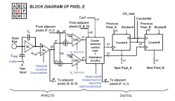
The Analog front end consists of a pre-amplifier followed by a window discriminator which has upper and lower threshold levels. The discriminator has four bits for threshold adjustment as well as polarity sensing. This allows the capture window to be precisely set. The rest of the digital electronics – multiplexers, shift registers, shutter and logic control – helps extract the data.
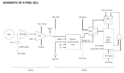
Further development of the Medipix (Tech Brief, PDF) devices led to a separate version called Timepix (Tech Brief, PDF). These new devices, besides being able to count photons, are capable of two additional modes. The first mode records “Time-Over-Threshold”, providing rough analog information about the energy of the photon. It does this by counting clock pulses for the duration when the signal stays above the discrimination levels. The other mode, “Time of Arrival”, measures arrival time of the first particle to impinge on the pixel. The counters record time between a trigger and detection of radiation quanta with energy above the discrimination level, allowing time-of-flight applications in imaging.
Medipix3 pixel schematic
Timepix2 pixel schematic
Besides medical imaging, the devices have applications in space, material analysis, education and of course, high energy physics. Hopefully, in a few years, hackers will lay their hands on these interesting devices and we can get to know them better. At the moment, the Medipix website has some more details and data sheets if you would like to dig deeper. For an overview on the development of such single photon detectors, check out this presentation from CERN – “Single X-Ray Photon Counting Systems: Existing Systems, Systems Under Development And Future Trends” (PDF).
It started as a joke, as sometimes these things do. [Marek Więcek] thought building a personal radiation detector would not only give him something to work on, but it would be like having a gadget out of the Fallout games. He would check the data from time to time and have a bit of a laugh. But then things got real. When he started seeing rumors on social media that a nearby nuclear reactor had suffered some kind of radiation leak, his “joke” radiation detector suddenly became serious business.
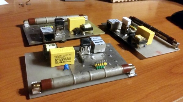
With the realization that having his own source of detailed environmental data might not be such a bad idea after all, [Marek] has developed a more refined version of his original detector (Google Translate). This small device includes a Geiger counter as well as sensors for more mundane data points such as temperature and barometric pressure. Since it’s intended to be a stationary monitoring device, he even designed it to be directly plugged into an Ethernet network so that it can be polled over TCP/IP.
[Marek] based the design around a Soviet-era STS-5 Geiger tube, and outfitted his board with the high voltage electronics to provide it with the required 400 volts. Temperature, barometric pressure, and humidity are read with the popular Bosch BME280 sensor. If there’s no Ethernet network available, data from the sensors can be stored on either the built-in SPI flash chip or a standard USB flash drive.
The monitor is powered by a PIC32MX270F256B microcontroller with an Ethernet interface provided by the ENC28J60 chip. In practice, [Marek] has a central Raspberry Pi that’s polling the monitors over the network and collecting their data and putting it into a web-based dashboard. He’s happy with this setup, but mentions he has plans to add an LCD display to the board so the values can be read directly off of the device. He also says that a future version might add WiFi for easier deployment in remote areas.
[Mike Harrison] produces so much quality content that sometimes excellent material slips through the editorial cracks. This time we noticed that one such lost gem was [Mike]’s reverse engineering of the 6th generation iPod Nano display from 2013, as caught when the also prolific [Greg Davill] used one on a recent board. Despite the march of progress in mobile device displays, small screens which are easy to connect to hobbyist style devices are still typically fairly low quality. It’s easy to find fancier displays as salvage but interfacing with them electrically can be brutal, never mind the reverse engineering required to figure out what signal goes where. Suffice to say you probably won’t find a manufacturer data sheet, and it won’t conveniently speak SPI or I2C.
After a few generations of strange form factor exploration Apple has all but abandoned the stand-alone portable media player market; witness the sole surviving member of that once mighty species, the woefully outdated iPod Touch. Luckily thanks to vibrant sales, replacement parts for the little square sixth generation Nano are still inexpensive and easily available. If only there was a convenient interface this would be a great source of comparatively very high quality displays. Enter [Mike].
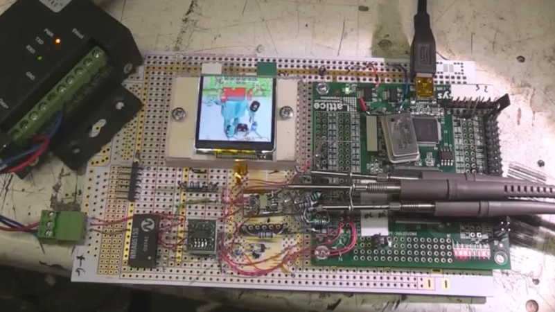
Outer edge of FPGA and circuit
This particular display speaks a protocol called DSI over a low voltage differential MIPI interface, which is a common combination which is still used to drive big, rich, modern displays. The specifications are somewhat available…if you’re an employee of a company who is a member of the working group that standardizes them — there are membership discounts for companies with yearly revenue below $250 million, and dues are thousands of dollars a quarter.
Fortunately for us, after some experiments [Mike] figured out enough of the command set and signaling to generate easily reproduced schematics and references for the data packets, checksums, etc. The project page has a smattering of information, but the circuit includes some unusual provisions to adjust signal levels and other goodies so try watching the videos for a great explanation of what’s going on and why. At the time [Mike] was using an FPGA to drive the display and that’s certainly only gotten cheaper and easier, but we suspect that his suggestion about using a fast micro and clever tricks would work well too.
It turns out we made incidental mention of this display when covering [Mike]’s tiny thermal imager but it hasn’t turned up much since them. As always, thanks for the accidental tip [Greg]! We’re waiting to see the final result of your experiments with this.
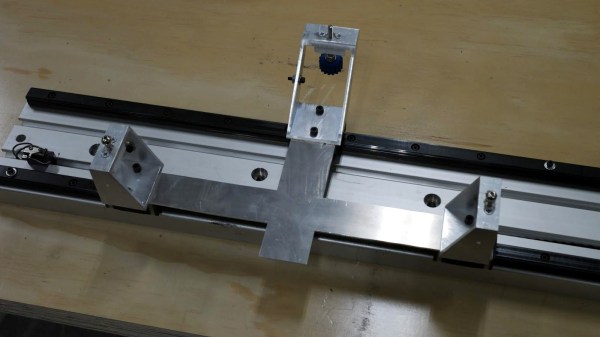
Aluminum bed with new kinematic mount and base on printer Son of Megamax, at the Milwaukee Makerspace
[Mark Rehorst] has been busy designing and building 3D printers, and Son of Megamax — one of his earlier builds — needed a bed heater replacement. He took the opportunity to add a Kelvin-type kinematic mount as well. The kinematic mount and base efficiently constrain the bed in a controlled way while allowing for thermal expansion, providing a stable platform that also allows for removal and repeatable re-positioning.
After a short discussion regarding the heater replacement, [Mark] explains the design and manufacture of his kinematic mount. Of particular note are the practical considerations of the design; [Mark] aimed to use square aluminum tubing as much as possible, with machining requirements that were easily done with the equipment he had available. Time is a resource after all, and design decisions that help one get something working quickly have a value all their own.
If you’re still a bit foggy on kinematic mounts and how they work, you’re not alone. Check out our coverage of this 3D-printed kinematic camera mount which should make the concept a bit clearer.


 Some months back, CERN announced
 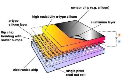 The Analog front end consists of a pre-amplifier followed by a window discriminator which has upper and lower threshold levels. The discriminator has four bits for threshold adjustment as well as polarity sensing. This allows the capture window to be precisely set. The rest of the digital electronics – multiplexers, shift registers, shutter and logic control – helps extract the data.