Humans are walking high voltage generators, due to all the friction with our surroundings, wide variety of synthetic clothes, and the overall ever-present static charges. Our electronics are sensitive to electrostatic discharge (ESD), and often they’re sensitive in a way most infuriating – causing spurious errors and lockups. Is there a wacky error in your design that will repeat in the next batch, or did you just accidentally zap a GPIO? You wouldn’t know until you meticulously check the design, or maybe it’s possible for you to grab another board.
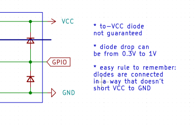 Thankfully, in modern-day Western climates and with modern tech, you are not likely to encounter ESD-caused problems, but they were way more prominent back in the day. For instance, older hackers will have stories of how FETs were more sensitive, and touching the gate pin mindlessly could kill the FET you’re working with. Now, we’ve fixed this problem, in large part because we have added ESD-protective diodes inside the active components most affected.
These diodes don’t just help against ESD – they’re a general safety measure for protecting IC and transistor pins, and they also might help avoid damaging IC pins if you mix. They also might lead to funny and unexpected results, like parts of your circuit powering when you don’t expect them to! However, there’s an awesome thing that not that many hackers know — they let you debug and repair your circuits in a way you might not have imagined.
Continue reading “Hacker Tactic: Internal ESD Diode Probing”