If there’s one thing that Hollywood knows about hackers, it’s that they absolutely love data visualizations. Sometimes it’s projected on a big wall (Hackers, WarGames), other times it’s gibberish until the plot says otherwise (Sneakers, The Matrix). But no matter what, it has to look cool. No hacker worth his or her salt can possibly work unless they’ve got an evolving Venn diagram or spectral waterfall running somewhere in the background.
Inspired by Hollywood portrayals, specifically one featured in Avengers: Age of Ultron, [Zack Akil] decided it was time to secure his place in the pantheon of hacker wall visualizations. But not content to just show meaningless nonsense on his wall, he set out to create something that was at least showing actual data.
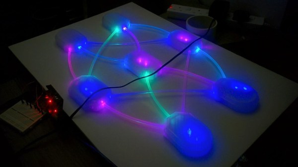
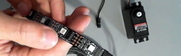
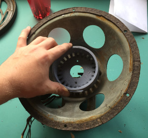
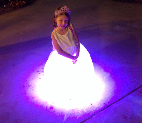
 [Zack] created a neural network to work through multi-label classification data in Python using the scikit-learn machine learning suite. The code takes the values from the neutral network training algorithm and converts them to RGB colors by way of an Arduino. Each “node” in the neutral network is 3D printed in translucent filament, and fitted with an RGB LED module. These modules are then connected to each other via side-glow fiber optic tubes, so that the colors within the tubes are mixed depending on the colors of the nodes they are attached to. This allows for a very organic “growing” effect, as colors move through the network node-by-node.
In the end this particular visualization doesn’t really mean anything; the data it’s working on only exists for the purposes of the visualization itself. But [Zack] succeeded in creating a practical visualization of machine learning, and if you’re the kind of person who needs to keep tabs on learning algorithms, some variation of this design may be just what you’re looking for.
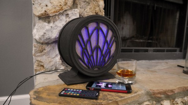
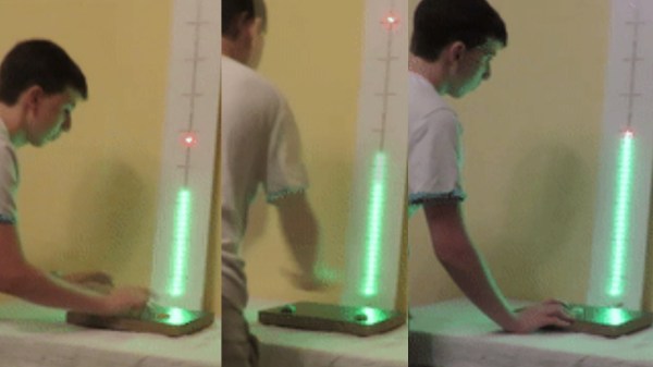
If AI isn’t your thing but you still want a wall of RGB LEDs, maybe you can use this phased array antenna visualizer instead. If you’re really hip, maybe you’ll go the analog route and put a big gauge on the wall.
Continue reading “Neural Network Really Ties The Room Together”


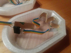
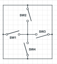 [Vejdemo-Johansson] figured a circle of 4 tilt sensors mounted on the one and twenty face would be enough to detect critical rolls. If any of the switches were tilted beyond 30 degrees, the switch would close. He mounted eight ball-tilt switches and glued in the LEDs. A hackerspace friend also helped him put together an astable multivibrator to generate the pulses for non-critical rolls.


