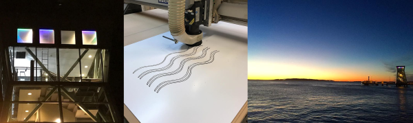
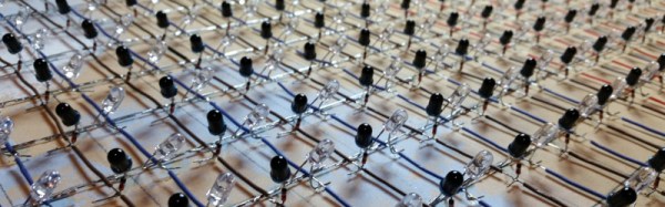
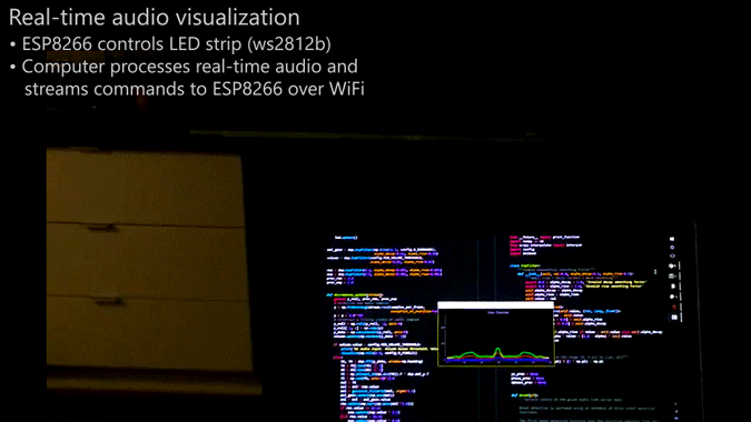
Making A Networked 32X32 LED Panel Case

[Adam Haile] of [Maniacal Labs] is at it again, whipping up some LED weirdness. This project is smaller than most of his work, though: he has made a nice case that holds a 32X32 LED matrix screen, the controller, and a Raspberry Pi. Check out the build and a brief demo in the video below.

This nice 3D printable design, called the Jumbo1K, would be a good starting point if you are looking to make something with one of these screens, as it provides easy access to all of the ports on the Pi for programming, debugging and networking the device without ruining the look. It does this with a neat trick, using the keystone jacks that you put in your wall when you are rewiring your house.
Continue reading “Making A Networked 32X32 LED Panel Case”

Blinktronicator’s POV Sends Our Eyebrows Rocketing Skyward

You think you’ve seen everything that there is to see regarding blinking LEDs and then a simple little trick proves you wrong. Our friend [Zach Fredin], aka [Zakqwy], added a pander mode to his blinky board which shows the Hackaday Jolly Wrencher in a Persistence of Vision mode. We love pandering, and obviously you just need to start the mode and wave the board back and forth. But in thinking the obvious you’d be wrong.

blinktronicator-board
Badass deadbug soldering to “fix” a mirrored shift register footprint

In the video after the break [Zach] demonstrates all the features of the blinktronicator and it’s recently finalized firmware. The tiny little board is a USB dongle featuring two buttons and an arc of sixteen LEDs in a rainbow of colors. When we say tiny, we mean it. Those LEDs are 0402 components and the board was small enough (and interesting enough) to receive an honorable mention in the Square Inch Project.

You would think that soldering all those LEDs by hand would be the trick, but [Zach] pulled off a much more difficult feat. Look closely at the image here (or click to embiggen). The two shift register footprints on the prototype were mirrored. He deadbug soldered each of them using — get this — the individual strands from some 28 AWG stranded wire. You sir, get the hardcore hand soldering badge and then some.

Okay, we’ll stop beating around the bush. The ATtiny45 on this board isn’t connected to the USB data lines, they’re only for power. That means, at its heart this is purely a blinking LED project, albeit one that uses the huge range of colors of the PICOLED family of parts. [Zach] did well with just two user inputs, but it’s the very simple POV party trick that really sucked us in. Instead of waving the board around, [Zach] uses a metal offset spatula as a mirror. Moving it back and forth unfolds the carefully timed flashes to draw your message in the air. Such a simple concept, but so satisfying to see it applied in a slightly different way.

Continue reading “Blinktronicator’s POV Sends Our Eyebrows Rocketing Skyward”

Bright Idea For A Name Tag

Looking for a quick DIY project to separate yourself from the crowd at your next business function or maker expo? Take a leaf out of [Pete Prodoehl’s] book and make your own name tag complete with blinking LED!

Minimalist, yet flashy (sorry!), this quick project can be completed inside a few hours with few resources, and is a great way to display your DIY handiwork. Continue reading “Bright Idea For A Name Tag”

Soldering Challenge To Challenge You

[Rick] knew that the blinking, beeping microcontroller kits that are commonly used for educational soldering workshops just would not cut it for a serious combat among SMD reworking professionals. The “Soldering Challenge” he created to fill this gap is a little PCB with eight difficulty levels from large through hole components to the smallest hand solderable SMDs. After assembly, the circuit assesses the skill level of the soldering aspirant based on a built-in scoring system.

soldering_challenge_ongoingThe challenge is meant to be played on a time limit. There are no two same-sized components of different value, so contestants may focus on soldering fast. Little rubber pads on the backside of the board provide for good ground contact in the curves. After the starting signal, you will be confronted with a few through hole resistors, a capacitor, different LEDs and a DIP-8 IC. Here it’s all about the speed and efficiency as you tackle a track full of bends and cut-off resistor legs. Over the course of the challenge, the components get smaller and smaller, until you finally reach the 0603 level, with a tiny SC-85 MOS-FET and a TSSOP 555 timer at the finishing line.
Continue reading “Soldering Challenge To Challenge You”

FPGA Powers Blazingly Fast LED Matrix Audio Visualizer

[Sam Miller], [Sahil Gupta], and [Mashrur Mohiuddin] worked together on a very fast LED matrix display for their final project in ECE 5760 at Cornell University.

Real time!
Real time!

They started, as any good engineering students, by finding a way to make their lives easier. [Sam] had built a 32×32 LED matrix for another class. So, they made three more and ended up with a larger and more impressive 64×64 LED display.

They claim their motivation was the love of music, but we have a suspicion that the true reason was the love all EEs share for unnaturally bright LEDs; just look at any appliance at night and try not be blinded.

The brains of the display is an Altera DE2-115 FPGA board. The code is all pure Verilog. The FFT and LED control are implemented in hardware on the FPGA; none of that Altera core stuff. To generate images and patterns they wrote a series of python scripts. But for us it’s the particle test shown in the video below that really turns our head. This system is capable of tracking and reacting to a lot of different elements on the fly why scanning the display at about 310 FPS. They have tested display scanning at twice that speed but some screen-wrap artifacts need to be worked out before that’s ready for prime time.

The team has promised to upload all the code to GitHub, but it will likely be a while before the success hangover blows over and they can approach the project again. You can view a video interview and samples of the visualizations in the videos after the break.

Thanks to their Professor, [Bruce Land], for submitting the tip! His students are always doing cool things. You can even watch some of his excellent courses online if you like: Here’s one on the AVR micro-controller.

Continue reading “FPGA Powers Blazingly Fast LED Matrix Audio Visualizer”

Tiny Tiny RGB LED Displays

Hackaday.io contributor extraordinaire [al1] has been playing around with small LEDs a lot lately, which inevitably leads to playing around with large groups of small LEDs. Matrixes of tiny RGB LEDs, to be precise.

Where's the LED?
Where’s the LED?

First, he took 128 0404 SMD RGB LEDs (yes, 40 thousandths of an inch on each side) and crammed them onto a board that’s just under 37 mm x 24 mm. He calls the project 384:LED (after all, each of those 128 packages has three diodes inside). A microcontroller and the driver chips are located on a separate driver board, which piggy-backs via pin headers to the LED board. Of course, he had to use 0.05 inch headers, because this thing is really small.

Of course, no project is without its hitches. [al1] bought LEDs with the wrong footprint by mistake, so he had a bunch of (subtly different) 0404 LEDs left over. Time for an 8×8 matrix! 192:LED isn’t just the first project cut in half, though. It’s a complete re-design with a four-layer board and the microcontroller on the back-side. And as befits a scrounge project with lots of extreme soldering, he even pulled the microcontroller off of a cheap digital FM radio. Kudos!

We’re in awe of [al1]’s tiny, tiny hacking skills. Now it’s time to get some equally cool graphics up on those little displays.

540 LEDs On A Geodesic Sphere

[burgerga] loves attending Music Festivals. He’s also a MechE who loves his LED’s. He figured he needed to put it all together and do something insane, so he build a huge, 15″ geodesic sphere containing 540 WS2812B addressable LED’s. He calls it the SOL CRUSHER. It sips 150W when all LED’s are at full intensity, making it very, very, bright.

As with most WS2812B based projects, this one too is fairly straightforward, electrically. It’s controlled by four Teensy 3.2 boards mounted on Octo WS2811 adapter boards. Four 10,000 mAh 22.2V LiPo batteries provide power, which is routed through a 5V, 30Amp heatsinked DC-DC converter. To protect his LiPo batteries from over discharge, he built four voltage monitoring modules. Each had a TC54 voltage detector and an N-channel MOSFET which switches off the LiPo before its voltage dips below 3V. He bundled in a fuse and an indicator, and put each one in a neat 3D printed enclosure.

The mechanical design is pretty polished. Each of the 180 basic modules is a triangular PCB with three WS2812B’s, filter capacitors, and heavy copper pours for power connections. The PCB’s are assembled in panels of six and five units each, which are then put together in two hemispheres to form the whole sphere. His first round of six prototypes set him back as he made a mistake in the LED footprint. But it still let him check out the assembly and power connections. For mechanical support, he designed an internal skeleton that could be 3D printed. There’s a mounting frame for each of the PCB panels and a two piece central sphere. Fibreglass rods connect the central sphere to each of the PCB panels. This lets the whole assembly be split in to two halves easily.

It took him over six months and lots of cash to complete the project. But the assembly is all done now and electrically tested. Next up, he’s working on software to add animations. He’s received suggestions to add sensors such as microphones and accelerometers via comments on Reddit. If you’d like to help him by contributing animation suggestions, he’s setup a Readme document on Dropbox, and a Submission form. Checkout the SolCrusher website for more information.

Thanks [Vinny Cordeiro], for letting us know about this build.

Continue reading “540 LEDs On A Geodesic Sphere”