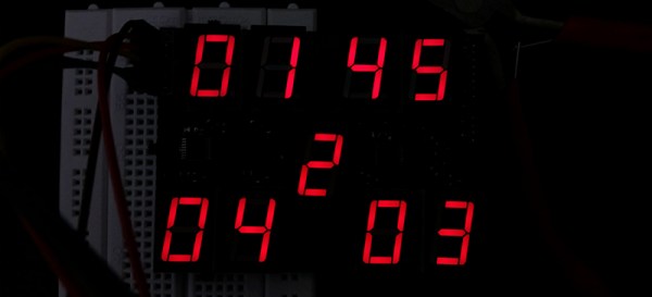
[Kratz] is working on a WiFi controlled scoreboard, but before building the full-scale version, he thought it would be wise to test out the multiplexing technique for the display. The experiment worked, but unless this scoreboard is for a foosball table, he still has a lot of work ahead of him.
The design of this prototype display is pretty simple, with just two ‘595 shift registers feeding bits to the display. Sixteen NPN transistors are being used to sink and source current to the display. It’s a relatively simple circuit, allowing [Kratz] to fit nine seven-segment displays on a small board with only six wires – ground, two V+ for the logic and LEDs, clock, data, and latch – going to the microcontroller.
There were a few snags in the design; the data is clocked in on a rising edge, but an extra falling edge was required before latching. [Kratz] can’t figure out the reason for this, and it might just be a timing issue.
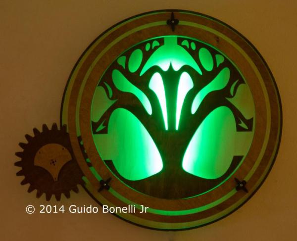
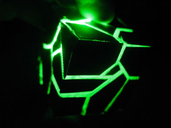
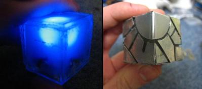 The exterior is thin sheet metal cut into cool shapes and bent around the plastic cube. Like the rest of the components, these metal covers are held on with hot glue. They do a great job of blocking the LED light ensuring it shines out of the creatively arranged gaps. We’re not sure if these will convince anyone that [AlexTheGreat] is from the future but they are certainly darn cool looking!