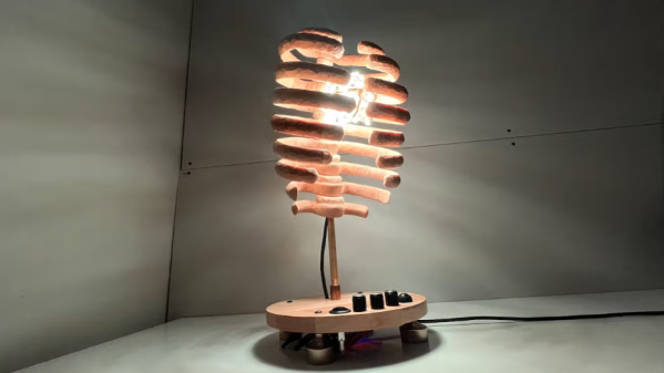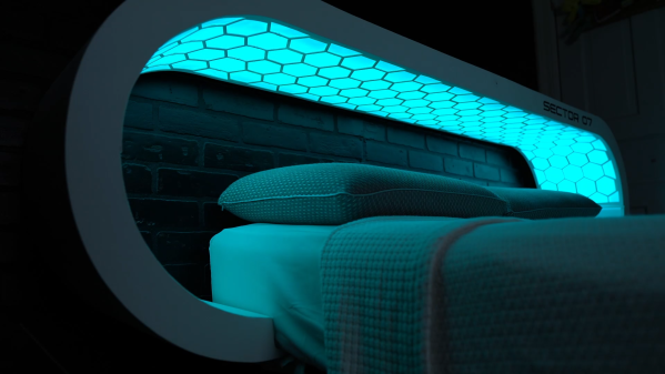
Despite the proliferation of artificial lighting, humans are still highly dependent on sunlight for regulation of our circadian rhythms. Accordingly, [Sector 07] has built a futuristic headboard that can help with the waking up side of things whether you’re headed to space or just in the dead of winter.
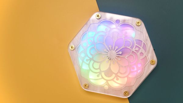
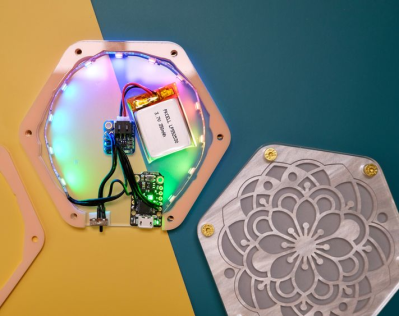
The interior of the headboard includes custom 3D printed panels to mount the electronics and a light diffusion screen made of nylon fabric. The printed parts were all joined by “welding” the pieces with a soldering iron and extra filament. Besides the futuristic hexagon motif in the diffusion screen, the most eye-catching part of this build is the curved ends making it look like a set piece from Star Trek: TNG. [Sector 07] was able to get the unique shape by kerf bending the plywood ends before joining them to the flat sections with dowels and wood glue.
Since this build also includes an integrated coffee maker and voice assistant, there’s a bit more going on with the electronics than you might have in a normal circadian lamp. Powering the project are two Arduino Mega boards and a SpeakUp Click that handles the voice commands. Wake-up times are controlled via a keypad, and the voice assistant, Prisma, will ask if you are awake once the 30 minute sun simulation has completed before your alarm goes off. If you don’t confirm wakefulness, Prisma will escalate alarms until the system is sure you’re awake and then will ask if you want coffee. If you want a deep dive into the system’s functionality, be sure to checkout the video after the break.
We’ve covered artificial suns before, so if you’re interested in trying to build you’re own you should check out this Hugely Bright Artificial Sun, a Sunrise Alarm Clock Mounted Above the Bed, and this Artificial Sun Via Old Satellite Dishes.
Continue reading “This Headboard Contains An Artificial Sun”