Teardowns of cheap electronic devices can produce results that are interesting, horrifying, or both, especially when mains power is involved. [bigclivedotcom] gave a minimalist LED lamp his reverse engineering treatment, and discovered a new chip that requires only four additional passive components to run LEDs on AC power.
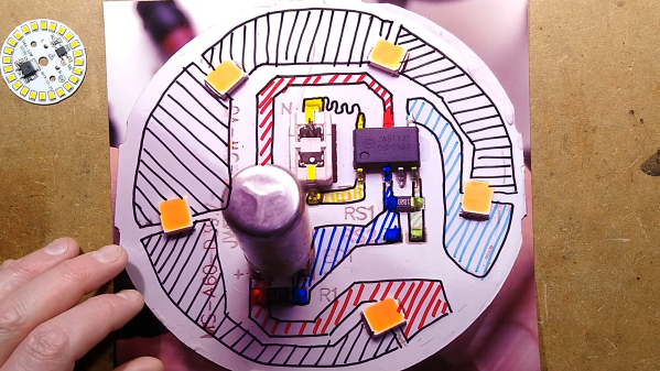
The chip in question is a Joulewatt JWB1981, for which no datasheet is available on the internet. However, there is a datasheet for the JW1981, which is a linear LED driver. After reverse-engineering the PCB, [bigclivedotcom] concluded that the JWB1981 must include an onboard bridge rectifier. The only other components on the board are three resistors, a capacitor, and LEDs. The first resistor limits the inrush current to the large smoothing capacitor. The second resistor is to discharge the capacitor, while the final resistor sets the current output of the regulator.
It is possible to eliminate the smoothing capacitor and discharge resistor, as other LED circuits have done, which also allow the light to be dimmable. However, this results in a very annoying flicker of the LEDs at the AC frequency, especially at low brightness settings.
As always, this is a very informative video from [bigclivedotcom], and it was all done based on a single picture of the PCB sent in by a viewer. He also mentions that the lifespan of the lamp would likely be increased by swapping out the current setting resistor for a larger one.
We’ve covered several [bigclivedotcom]’s videos, covering topics from self-powered wireless switches to filling up fake capacitors with electrolyte.
Continue reading “Investigating A New Chip In A Minimalist LED Lamp”