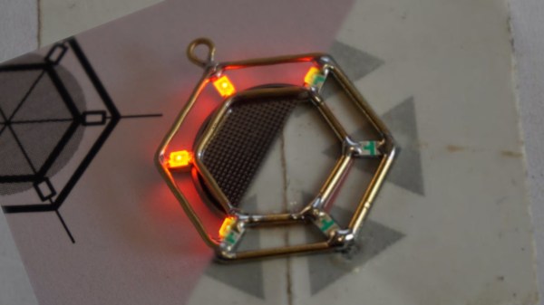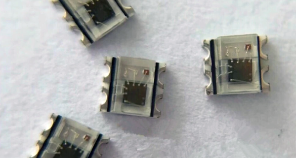
The WS2812, or “Neopixels”, or whatever you want to call them, are the standard when it comes to adding blinky to anything. These chips are individually addressable RGB LEDs, which you’ve seen in many LED strips and a thousand other products. These LEDs are rather big compared to normal, dumb LEDs, measuring 5 mm on each side. Here are WS2812s packed into a 2 mm x 2 mm square package. It’s the smallest and brightest blinky that works the same as the WS2812s you know and love.
This is the latest product from Worldsemi. We’ve heard of these before, but damned if we could find a supplier or even a price. Now they’re on AliExpress, at a price of $8 USD per 100, shipping not included.
Electrically, these appear to have the same properties of the normal, 5050-size WS2812 LEDs. Apply power and ground to two pins, send data in on one pin, and connect the next LED in the strand to the remaining pin. Yes, it requires a bit of work to turn this into a display, but microcontrollers are very fast now and have plenty of RAM. Attach a BeagleBone and you’ll be able to drive as many as your glowing heart desires.
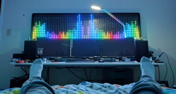
If you’re wondering what the coolest project imaginable for these LEDs is, here’s the math: the largest (common) PCB panel for your random board house is 16 by 22 inches. Assuming a 3 mm pixel pitch, that means the largest PCB display you can make with these LEDs is 135 by 186 pixels, call it 120 by 180 just to make things easy. That’s 21,600 LEDs, at a cost of about $2,000. I would not recommend reflowing these, and assuming soldering a LED every thirty seconds, it will take about a month to solder them all by hand. There’s your project, now get to it.