Some of the most satisfying projects of all are the ones that do something visual. All the network routers, data loggers, and thermostats are great. But we are visual creatures and even a humble blinking LED is enough to give you a little rush even compared to finding a large prime number. We wanted to see what our community could do visually with a Raspberry Pi so we challenged you with the Visualize it with Pi contest.
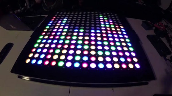
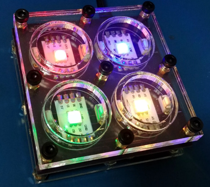
As always, the competition was brisk, with a lot of great projects. This contest showed off the trend towards using LED modules and assemblies to add visuals to projects. Why not? They are cheap enough and a well-integrated module can make a project simple to wire and integrate.
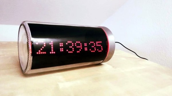
We didn’t see as many media-related projects as you might expect, although there was one tied into Stranger Things, one to Tron, and the virtual reality lighting project did have some Star Wars images. Projects ranged from the practical storage box labels to the whimsical lemonade bottle that strobes to the beat of the music. If none of that is hardcore enough for you, there was even a Raspberry Pi-controlled radio telescope. You can find all the entries over on Hackaday.io. Now let’s see which entries managed to turn the head of the judging panel.
Continue reading “Contest Results: Raspberry Pis Put On A Show”

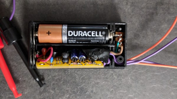
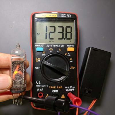 The device’s low current means that nixie and neon elements won’t light up very brightly, but they will light up enough to verify function and operation. [The LED Artist] reports that touching the output terminals of the generator only causes a slight tingling sensation.