Run Your Favorite 8-bit Games On An ESP32

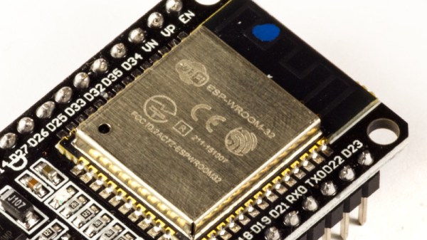
Here at Hackaday HQ we’re no strangers to vintage game emulation. New versions of old consoles and arcade cabinets frequently make excellent fodder for clever hacks to cram as much functionality as possible into tiny modern microcontrollers. We’ve covered [rossumur]’s hacks before, but the ESP_8-bit is a milestone in comprehensive capability. This time, he’s topped himself.

There isn’t much the ESP 8-bit won’t do. It can emulate three popular consoles, complete with ROM selection menus (with menu bloops). Don’t worry about building a controller, just connect any old (HID compliant) Bluetooth Classic keyboard or WiiMote you have at hand. Or if that doesn’t do it, a selection of IR devices ranging from joysticks from the Atari Flashback 4 to Apple TV remotes are compatible. Connect analog audio and composite video and the device is ready to go.

The system provides this impressive capability with an absolute minimum of components. Often a schematic is too complex to fit into a short post, but we’ll reproduce this one here to give you a sense for what we’re talking about. Come back when you’ve refreshed your Art of Electronics and have a complete understanding of the hardware at work. We never cease to be amazed at the amount of capability available in modern “hobbyist” components. With such a short BOM this thing can be put together by anyone with an ESP-32-anything.

There’s one more hack worth noting; the clever way [rossumur] gets full color NTSC composite video from a very busy microcontroller. They note that NTSC can be finicky and requires an extremely stable high speed reference clock as a foundation. [rossumur] discovered that the ESP-32 includes a PLL designed for audio work (the “APLL”) which conveniently supports fractional components, allowing it to be trimmed to within an inch of the desired frequency. The full description is included in the GitHub page for the project and includes detailed background of various efforts to get color NTSC video (including the names of a couple hackers you might recognize from these pages).

Continue reading “Run Your Favorite 8-bit Games On An ESP32”

Smart Home Meets Dumb Terminal

Most smart home products are designed to be controlled from a mobile device, which makes sense since that’s what the average consumer spends most of their day poking around on these days. But you aren’t the average consumer, are you? If you’re looking for a somewhat more tactile experience, then why not put your smart home dashboard on a vintage serial terminal as [Daniel Karpantschof] did?

So how do you get the latest and greatest in home automation talking to a serial terminal built before the Internet as we know it? With Python, of course. [Daniel] has some code running on a Linux server that’s actually taking to his various smart home gadgets, which then spits out a simple ASCII user interface that his circa 1976 ADM-3A terminal can handle; complete with a floor plan view of the house that shows the temperature in different rooms.

Naturally, that’s only half the battle. You still need to get that interface onto the terminal. For that, [Daniel] is using the “Simulant Retro WiFi Modem” that we’ve covered in the past. An ESP8266 connects to the network and shuffles data over to the target device over serial. It’s all transparent to the terminal itself, so this project could be reproduced with whatever vintage machine holds a special place in your heart.

A DIY Electronic Load With A Twist

If you’re testing a power supply or battery pack, an electronic load is a nice tool to have. By watching the voltage as you crank up the resistance, you can verify the unit’s real-world capabilities quickly and easily. But [Xavier Bourlot] wanted a bit more information than is generally afforded by these devices, so he came up with his own scratch built load that can measure the voltage at multiple points in the circuit.

Now at first glance, it might not be obvious why you’d want such a capability. But [Xavier] is looking to do something very specific with this device: analyze the efficiency of DC-DC converters. The idea is that if the electronic load can measure the voltage on both sides of the converter, it can calculate what kind of losses are being incurred.

Could you do this with a multimeter and a traditional electronic load? Sure. But if it’s the kind of thing you’ll be doing a lot of, it’s not hard to see why this method would be preferable.

But even if you ignore the converter analysis capabilities, this looks to be a very useful device to have around the lab. [Xavier] says it can sink more than 5 amps, and handle an input voltage as high as 100 volts. Powered by an ATmega328P, the load is also fully programmable and even features an I2C expansion port that you can use to hang additional hardware or sensors on. The stock firmware is already quite capable, and the list of future enhancements has some very interesting entries such as the ability to log data over serial or to a SD card.

We’ve seen a number of programmable electronic load projects over the years, ranging from Arduino shields to VFD equipped units that would be the pride of any hacker’s bench.

Sparklines For Your ESP32 Projects

On a typical microcontroller project we may only have access to a relatively tiny screen. Information display can be a challenge, but it’s one that may be made easier by [0xPIT]’s ESParklines library for Espressif processors using the Arduino framework.

A sparkline is a simple line graph without annotations (like axes or units) intended to fit within the flow of text. They’re largely associated today with the statistician Edward Tufte, and if you’ve not encountered them or Tufte before then we suggest you’ll enjoy educating yourself.

It’s a simple enough library and it comes with example code. Usefully it maintains a data buffer all of its own allowing simple updating, and as well as the examples there is a YouTube video we’ve put below the fold showing graphs evolving as more information is added to them. We’re curious about one thing though, it’s billed as an ESP library, for either the ESP8266 or the ESP32, but we can’t find any ESP-specific code in there and neither could our friendly ESP-guru. Have we missed something? The comments are below if you can shed any light.

Continue reading “Sparklines For Your ESP32 Projects”

Adding WiFi To Black Magic For Wireless GDB Action

[Thoquz] wrote to us about an interesting GitHub project by [Valmantas Palikša] involving the porting of the Black Magic firmware to ESP8266. For those who are unaware, Black Magic Probe is firmware along with a range of official and third-party boards that targets the debugging of Cortex-M and Cortex-A MCUs and SoCs.

With this blackmagic-espidf project, one can use any ESP8266 board that has at least 2 MB of Flash program storage, though 1 MB should be possible if OTA updated are disabled. After flashing the firmware to the ESP8266 board, the GDB server can be reached on TCP port 2022 and UDP 2023, with a serial port available via TCP/23, UDP2323, or via the physical TX0/RX0 pins on the ESP8266.

The target board to be debugged  is hooked up by default to GPIO0 (SWDIO) and GPIO2 (SWCLK) for Serial Wire Debugging, though JTAG is also said to be supported. If set up properly, next one should be able to pop into a fresh remote GDB session:

gdb connection

If you don’t want the WiFi, you can buy a wired one, or just roll your own from any STM32 board that you’ve got kicking around.

Fusion For STM32: Development Board With Debugging And Programming Via WiFi

Clearly profiling itself as the Lamborghini or Ferrari of the STM32 development board world, MikroElektronika’s current (8th) revision of their Fusion development board was released last year with support for not only flashing but also debugging the attached STM32 MCU via the onboard WiFi module. The Serbian company’s pricing for the bare board without MCU modules or any other peripherals appears to be around 300 USD/Euro. Additional MCU boards cost between $28 – $60 each.

As the official product page explains, the board is combined with the CodeGrip software to manage the board either via USB-C (driver-free) – which also allows one to configure the WiFi option – and via WiFi. Peripheral boards are added via the 5 onboard MikroBUS expansion slots, either with existing boards, or custom MikroBUS boards. The power supply is also onboard, powered via USB, a barrel jack connector, or an external battery.

The use of WiFi to connect to the board would allow for it to be easily managed and debugged when it’s in a less convenient location than one’s desk, which would seem like a major boon.

Obviously it’s not a cheap board, and the MCU cards each cost about as much as a Nucleo or Discovery board from ST would cost, making it hard to justify purchasing it for anything but a professional environment. However, the tantalizing thing here is probably that so much of the design details are available, from the expansion bus to the pin-out and schematic of the MCU cards (STM32F767ZG version).

The MCU cards use the Hirose FX10A-168S-SV and FX10A-168P-SV(71) connectors, all readily available. This opens the possibility of developing compatible MCU cards. An MCU card template project can for example be found here.

The Easiest Way To Put Your Doorbell On The Internet

Thanks to low-cost WiFi enabled microcontrollers such as the ESP8266 and ESP32, it’s never been a better time to roll your own smart home system. But that doesn’t mean it isn’t daunting for new players. If you’re looking for an easy first project, putting your old school doorbell on the Internet of Things is a great start, but even here there’s some debate about how to proceed.

Most people stumble when they get to the point where they have to connect their low-voltage microcontroller up to the relatively beefy transformer that drives a standard doorbell. We’ve seen a number of clever methods to make this connection safely, but this tip from [AnotherMaker] is probably the easiest and safest way you’re likely to come across.

His solution only requires an inductive current sensor, which can be had for less than $1 from the usual overseas suppliers. One leg of the doorbell circuit is passed through the center of this sensor, and the sensor itself is connected up to your microcontroller of choice (here, and ESP32). The rest is software, which [AnotherMaker] explains in the video after the break. With the addition of a little debounce code, your microcontroller can reliably determine when somebody is out there jabbing the bell button; what you do with this information after that is up to you.

If you’re worried this method is too easy you could always try it with an optocoupler, or maybe convert the low-voltage AC to something your microcontroller can handle.

Continue reading “The Easiest Way To Put Your Doorbell On The Internet”