Expanded Memory For The Teensy++ 2.0

RAM

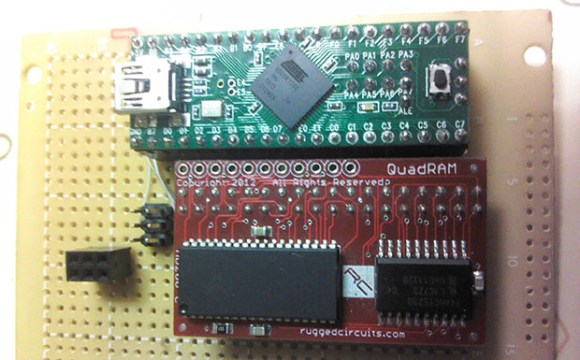
Sometimes with a microcontroller project you need to do some very RAM-hungry operations, like image and audio processing. The largish AVR chips are certainly fast enough to do these tasks, but the RAM on these chips is limited. [xxxajk] has come up with a library that allows the use of huge RAM expansions with the Teensy++ 2.0 microcontroller, making these RAM-dependant tasks easy on one of our favorite microcontroller board.

[xxajk]’s work is actually a port of XMEM2, an earlier project of his that added RAM expansion and multitasking to the Arduino Mega. Up to 255 banks of memory are available and with the supported hardware, the Teensy can address up to 512kB of RAM.

XMEM2 also features a preemptive multitasking with up to 16 tasks, the ability to pipe messages between tasks, and all the fun of malloc().

The build is fairly hardware independent, able to work with Rugged Circuits QuadRAM and MegaRAM expansions for the Arduino Mega as well as [Andy Brown]’s 512 SRAM expansion. With the right SRAM chip, etching a board at home for XMEM2 is also a possibility.

Dad-Built Rocket Control Module

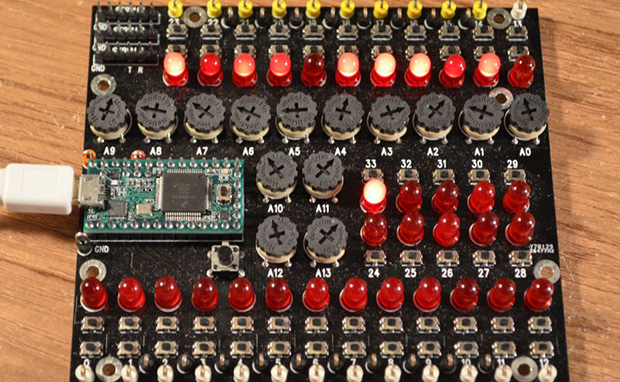
Like a lot of parents, [justbennett]’s kids like to play rocket and spaceship command. His kids’ imagination-assigned controls kept shifting from this LEGO to that banana to the dog’s tail, so [justbennett] did what he had to do: make this Dad-built rocket control module for them.

The module supports all of the vital sub-modules required for rocket and spaceship administration. There is a launch status indicator, an acceleration vector resonator (AVR), and a com-link. He used mostly parts on hand, and the Arduino count is zero. He built a NASA-grade Plexiglas enclosure to avoid juice box incidents. The two pieces are connected with aluminum angle bar so that he can make repairs or modifications.

The analogue joystick was a thrift store find. [Justbennett] wired the trigger and thumb buttons up as the AVR which activate a recycled PICAXE 08M project of his. The PICAXE senses the button pushes to flash an LED and play an ascending or descending tone. Long-pressing one button will result in an explosion noise as you might expect.

The launch status indicator is a potentiometer wired to a second PICAXE and three LEDs that light up in sequence. In the future, [justbennett] intends to add haptic feedback with a tiny vibration motor. The com-link packet messaging system is a Radio Shack recording module and two big, tempting buttons. The control module ships with a message from Star Command that explains the controls.

Nrf24l01+ Using 3 ATtiny85 Pins

[Ralph] wasn’t satisfied with the required 5 control pins to drive his nrf24l01+ transceiver module, so he used this circuit needing just 3 pin using an ATtiny85.

One of the key components was to effectively drive the chip select (CSN) line from the clock (SCK) line. The nrf24l01+ needs the CSN line to transition from high to low on the beginning of a communication.  [Ralph] put the SCK line behind a diode, put a capacitor in parallel with the CSN line and altered the arduino-nrf24l01 library to encode extra delays for the clock line.  This allowed the CSN line to be driven by the SCK line. Subsequent line transitions during transmission happen too fast to charge the capacitor, leaving the CSN line in a low state.

After tying the chip enable line high and dropping the 5V power line to 1.9-3.6V across a red LED, [Ralph] had an ATtiny85 controlling a nrf24l01+ module.

Though deceptively simple, a very cool hack that opens up a couple more lines on the ATtiny85.

The 128 Button, 6 Axis, 17 Slider, 4 POV Hat Switch Joystick Controller

stick

[Paul Stoffregen], creator of the Teensy series of dev boards, previously implemented a six-axis joystick for Teensyduino, the Arduino library for the Teensy. He had originally tried 8 axes, but a few problems cropped up, deadlines approached, and he left it as is. A few recent projects gave him some insight into how to implement a joystick with more than six axes as a USB HID device, so he started looking at how to read an improbable amount of pots and buttons for a USB joystick.

So far, the biggest problem is figuring out what software can actually use an HID joystick with this many controls. The answer to that question is none. The Linux-based jstest-gtk is able to read 6+17 pots, the four hat switches, but only 64 of the 128 buttons. A user on the Teensy forums, [Pointy], has been working on his own joystick test app that works on Linux Windows, but testing the joystick on Windows is an exercise in futility for reasons no one can figure out.

As for why anyone would want a six-axis, 17-slider, 128-button joystick, think about this: with this much control, it would be relatively simple to build the MIDI controller to end all MIDI controllers, or a cockpit simulator for everything from a C172, 737, to a Kerbal interplanetary cruiser. That’s an impressive amount of control, and all from a $20 Teensy dev board.

Further testing of this Teensy joystick is desperately needed, so if you’re able to help out drop a note in the forum thread.

Motion Tracking On The Cheap With A PIC

motion tracking

Ever need a cheap motion tracker for very basic object following? Did you know you can throw one together with a few IR distance sensors and a PIC?

The setup is fairly simple. [Aron Horan] is using a dsPIC30F4011 PIC, a SHARP infrared distance sensor, an RC servo, and a PICkit2 for testing. It works by scanning left and right using the servo motor. When the edge of an object is detected, it will turn away from the object until it can no longer detect the edge — then it turns back. Unfortunately this does mean it will always be twitching, even when it’s tracking an object.

Like many of the other projects [Aron] has documented, he’s included everything you need to know to be able to recreate the project yourself. Flowcharts, wiring diagrams, and the code — written in C of course! The following video includes an excellent demonstration, but if you want to skip straight to the action, you can see it start tracking a multimeter at about 0:39 in.

Continue reading “Motion Tracking On The Cheap With A PIC”

Java Grinder Spits Out DsPIC And MSP430 Assembly Code

java-code-grinder

[Michael Kohn] sent in a link to the set of projects he’s been working on lately. The Java Grinder is a project that converts Java code for use on microcontrollers. This actually started back in 2009, when he mentioned that the project was worthless because there were already a ton of Java virtual machines out there. But if he had really thought that he’d never learn anything. We’re glad [Michael] picked this back up and made something out of it.

The image above shows the proof of concept. It’s a box bouncing around the Nokia 6100 screen. He wrote the animation in Java, and used his grinder to turn the code into dsPIC assembly, which was then compiled and flashed onto the microcontroller. That’s not all, he’s also coded a Mandelbrot set generator or the same hardware. As it stands he can also produce assembly code for use on MSP430 chips.

This kind of exploration is great for the brain. We see it as a natural extension of the learning you acquire from Nand2Tetris which walks through the essential text The Elements of Computing Systems. If you’re not familiar, that’s a trip from building your first logic gate, which you plunk together with others to build an ALU, then start coding all the way up to a virtual machine to run on your simulated hardware.

Video of the bouncing box and Mandelbrot set is below.

Continue reading “Java Grinder Spits Out DsPIC And MSP430 Assembly Code”

Single Digit Numitron Clock

numitronClock

The above may look like a Nixie tube, but it’s a Numitron: the Nixie’s lower-voltage friend, and part of [pinomelean’s] single-digit Numitron clock. If you’re unfamiliar with Numitrons, we suggest you take a look at our post from a few years ago, which includes a helpful tutorial to catch you up to speed.

[pinomelean] built this little device to capture a steampunk-ish look on the cheap for a clock small enough to fit on a wrist. The build uses a PIC16F84A uC and a 4MHz crystal on a custom PCB. A small button on the side lets the wearer set the time. Similar to the Vibrating Timepiece from last month, the Numitron clock isn’t perfect, though it is more accurate: gaining only one minute every 3 days.

Check out the video after the break to see it being set and keeping track of the time. It may take a moment to understand how to read the clock, though. Each of the four LEDs indicates where the number in the Numitron tube belongs. The LEDs light in sequence from left to right, displaying the clock one digit at a time.

Continue reading “Single Digit Numitron Clock”