Remote Servo-controlled Lightswitch

remoteServoLightSwitch

We frequently get home automation tips, many of which have simple circuit-based on/off control for lights. [Paulo Borges] has created something quite different, however, with his in-the-wall servo-controlled light switch. This build forgoes the need of any relay to switch mains power, and because it’s physically flipping your switch, provides a distinct advantage over other builds that require a phone or tablet interface: you can use your switches as you normally would.

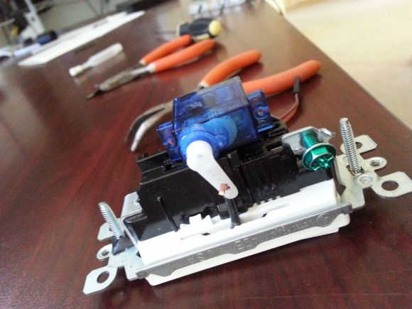
[Paulo] picked up a rocker-type switch at the local hardware store and carefully pried off the large, flat switch plate to notch out a small hole at its fulcrum. He then carefully shaped a piece of 12 gauge wire to provide a pivot point for the servo. His choice to use wire here seems to be entirely to provide a sturdy yet bendable component that functions mechanically rather than electrically. A small 9G servo fits to the back of the switch’s housing, and the servo’s arm connects up to the previously attached 12 gauge wire. He pieced together the remote control feature with an RF link kit with an inexpensive 433mhz Code duplicator from eBay.

[Paulo] explains that his Instructable is simply an overview rather than a step-by-step guide, so if you’re eager to reproduce this hack you’ll have to work out the code and the remote control portion yourself. He also acknowledges the biggest remaining hurdle: finding space in the wall to shove all the microcontroller guts. Check out a couple of videos of the switch after the break, and remember, there’s always the option of doing away with all light switches.

Continue reading “Remote Servo-controlled Lightswitch”

LED Costumes And Clothing

3ledCostume

Our tips line recently received an influx of wearable LED projects, both for casual and professional wear. [Elizabeth] and [Luis] have created the Lüme wearable collection, aimed at accessorizing by adding adjustable accent colors to jackets, t-shirts and dresses. The electronics are custom-made, built around an ATMega32u4, and each is Bluetooth enabled to interact with a user’s cell phone. From the phone, you can change colors, sequences, set up events, and even take advantage of an “inkdropper-style” feature that matches the color of the LEDs to any object you point your camera at.

[Michal’s] project is an entire suit for a dance and laser show entitled “Tron Dance”, which uses several RGB LED strips placed on key points of the wearer’s costume. It looks like [Michal] has intentionally avoided the joint areas to prevent any problems with breaks or bends, but still manages to place enough to cover the entire body. We aren’t sure what controls everything, but you can watch it go through various sequences and survive an onstage performance after the break.

Finally, in yet another kind of performance, magician [Kiki Tay] has built a jacket that’s overflowing with RGB LEDs. [Kiki] wanted wearable LED control that could be used in various situations without having to re-invent the wheel each time, so he developed his own board — the LED Magician: an Arduino-compatible solution. The board has 12 outputs channels, drives 50+ LEDs per channel and features 12 on-board LEDs that display a preview of the output. To make interactions user-friendly, [Kiki] has provided 32 built-in sequences and adjustable speeds that the user can program via 4 buttons on the board. If that isn’t enough control, there are some options for external control as well. The jacket itself runs off a hobby LiPo battery and is blindingly bright: stick around after the break for a video.

Continue reading “LED Costumes And Clothing”

Smart Citizen: Arduino-compatible And Packed With Sensors

smartCitizenBoard

If you’re going to develop another Arduino-compatible board these days, you might as well take a “kitchen sink” approach. The Smart Citizen Kit piles it on, including Wi-Fi, an SD card slot, and EEPROM on its base. The attached shield—dubbed the “Ambient Board”—is a buffet of sensors: temperature, humidity, CO, NO2, light intensity, and a microphone for reading sound levels. The board’s intended purpose is to provide an open-source, interactive, environmental database by crowdsourcing data from multiple Smart Citizen Kits, but you can add your own stuff or yank the shield off altogether. Additional shields are also under development, aimed at providing agricultural data, monitoring biometrics, and more.

Stick the Smart Citizen somewhere and it can send sensor data to the web over a WiFi connection. The result is worth a look. Here’s the map with the real-time data from early release models scattered over Europe, most of which appear to be solar-powered with a small LiPo battery to keep them going overnight. There’s also an accompanying iPhone app that lets you set up the Smart Citizen, retrieve data from nearby sensors, and allows you to match your phone’s GPS location to any data you collect while carrying the board around.

The developers met their Kickstarter goals earlier this summer and the board has recently entered the manufacturing process, Rummage through their GitHub files here, and watch a video preview of the Smart Citizen below.

Continue reading “Smart Citizen: Arduino-compatible And Packed With Sensors”

Passive Bluetooth Keyless Entry System

Modern smart keys allow you to keep the key fob in your pocket or purse while you simply grab the handle and tug the door open. [Phil] decided he would rather ditch the fob altogether and instead implemented a passive Bluetooth keyless entry system with his Android phone. It’s probably unlikely for car manufacturers to embrace phone-based keys anytime soon, and [Phil] acknowledges that his prototype poses a landslide of challenges. What he’s built, however, looks rather enticing. If the car and phone are paired via Bluetooth, the doors unlock. Walk out of range and the car automatically locks when the connection drops.

His build uses an Arduino Mega with a BlueSMiRF Silver Bluetooth board that actively searches for his phone and initiates a connection if in range.  Doors are unlocked directly through a 2-channel relay module, and an LED indicator inside the vehicle tells the status of the system. A pulsing light indicates it’s searching for the phone, while a solid ring means that a connection is established.

We hope [Phil] will implement additional features so we can make our pockets a bit lighter. Watch a video demonstration of his prototype after the break, then check out the flood of car-related hacks we’ve featured around here recently: the OpenXC interface that adds a smart brake light, or the Motobrain, which gives you Bluetooth control over auxiliary electrical systems.

Continue reading “Passive Bluetooth Keyless Entry System”

Inside The Clapper

clapper

Hackaday readers above a certain age will probably remember the fabulously faddish products developed by Joseph Enterprises. These odd gadgets included the Ove’ Glove, VCR Co-Pilot, the Creosote Sweeping Log, and Chia Pet (Cha-Cha-Cha-Chia) as mainstays of late night commercials, but none were as popular as The Clapper, everyone’s favorite sound-activated switch from the 1980s. [Richard] put up a great virtual teardown of The Clapper, that provides a lot of insight into how this magic relay box actually works, along with some historical context for the world The Clapper was introduced to.

Sound activated switches are nothing new, but the way The Clapper did it was just slightly brilliant. Instead of listening to every sound, the mic inside the magic box sends everything through a series of filters to come up with a very narrow bandpass filter centered around 2500 Hz. This trigger is analyzed by a SGS Thompson ST6210 microcontroller ( 4MHz, ~1kB ROM, 64 bytes of RAM, and 12 I/O pins ) to listen for two repeating triggers  within 200 milliseconds. The entire system – including the source code for the MCU – can be seen in the official patent, US5493618.

The Clapper sold many millions of units at a time when a lot of homes were assuredly in a pre-microelectronics world. Yes, in 1986, a lot of TVs had microcontrollers and maybe a washer/dryer combo may have had a few thousand transistors between them. Other than that, The Clapper was many household’s introduction to the ubiquitous computing power we see today, and all with less capability than an Arduino.

Arduino-based Temp Control Via SMS

smsTempController

As connected as we are, reliable and affordable internet is still a luxury in the far reaches. [kohleick’s] country home is not just remote; with temperatures dropping to -30C in the winter, it’s practically Arctic. His solution for controlling the thermostat from afar was to take advantage of the GSM network and implement a SMS-based heater controller. The unit typically operates in “antifreeze mode,” but sending a simple text message prior to visiting causes the heater to kick it up to a more comfortable setting for your arrival. Daily logs report the system’s status, and an alert will trigger when temperatures fall below a set limit, thus indicating potential faults with the heater.

The build uses a Freeduino paired with an external GSM modem for communication and an LCD to display current status and menus, which users access via three buttons on the side of the picture frame. [kohleick] connected two temperature sensors: one directly to the Freeduino’s shield and a second outside the house. After the temperature sensors detect deviance from the set point, or upon SMS instruction, the Freeduino will crank up the heat through a 5V relay attached to the home’s boiler. Head over to the Instructables page linked above for a bill of materials, schematics, and the code. The Siemens GSM modem in this build is nothing to worry about, but be careful if you try to reproduce this project with an Arduino GSM shield, or your house might really heat up.

Building A Brushless Motor Controller Around An ATmega Chip

You know when you see something like this it’s just going to be awesome, and we weren’t disappointed by our first impression. [Davide Gironi] built a brushless motor controller from the ground up using an ATmega8 as the brain. If you want to understand every aspect of a subject this is how to do it. Lucky for us he explains what each portion of the prototype does.

Brushless motors have no brushes in them (duh). But what does that really mean? In order to spin the motor a very carefully crafted signal is sent through the motor coils in the stationary portion (called the stator), producing a magnetic field that pushes against permanent magnets in the rotor. A big part of crafting that signal is knowing the position of the rotor. This is often accomplished with Hall Effect sensors, but can also be performed without them by measuring the back EMF in the coils not currently being driven. The AVR-GCC compatible library which [Davide] put together can be tweaked to work with either setup.

Get a good look at the system in action after the break.

Continue reading “Building A Brushless Motor Controller Around An ATmega Chip”