Solder Trick To Make Your Own Surface Mount Breakout Boards

surface-mount-breakout-trick

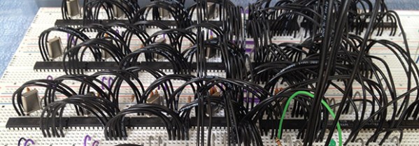
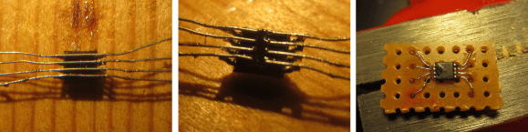
We think you’re really going to enjoy this trick for making surface mount breakout boards. It’s common to use magnet wire to connect individual pins of a surface mount part to breadboard friendly protoboard with pin headers. What’s new here (at least to us) is that [Raul] solders one wire to both pins directly across from one another.

The image at the left shows an eight pin part with four wires soldered in place. To get to this point he first taped the wires down to a work surface being careful to space them to match the pitch on the chip’s leads. He then tapes the chip in place and solders all of the legs to the wires. This seems to kill two birds with one stone as aligning one wire to one leg is tough. From there he flips the chip over and cuts the wire spanning under it. This leaves an easy job of soldering the trailing side of the wire to a hunk of protoboard.

It’s perfect for chips with a small number of pins. Of course you may still want an etched breakout board for something with a ton of leads.

16 Core Computer Made Of ATMegas

Your desktop has two, four, or even eight cores, but when’s the last time you’ve seen a multicore homebrew computer? [Jack] did just that, constructing the DUO Mega, a 16 core computer out of a handful of ATMega microcontrollers.

From [Jack]’s description, there are 15 ‘worker’ cores, each with their own 16MHz crystal and connection to an 8-bit data bus. When the machine is turned on, the  single ‘manager’ core – also an ATMega328 – polls all the workers and loads a program written in a custom bytecode onto each core. The cores themselves have access to a shared pool of RAM (32k), a bit of Flash, a VGA out port, and an Ethernet controller attached to the the master core.

Since [Jack]’s DUO Mega computer has multiple cores, it excels at multitasking. In the video below, you can see the computer moving between a calculator app, a weird Tetris-like game, and a notepad app. The 16 cores in the DUO Mega also makes difficult calculations a lot faster; he can generate Mandelbrot patterns faster than any 8-bit microcontroller can alone, and also generates prime numbers at a good click.

Continue reading “16 Core Computer Made Of ATMegas”

Ditch That Boring Mouse For A Military-grade Trackball

military-grade-trackball

The bad thing about this type of hack is that now [Tomek Dubrownik] needs to cut a hole in his desk to house the thing. He got this military grade trackball working over USB. It’s old, and could be used as a blunt weapon. But as the video shows it still makes a great input device.

He found the hardware on Allegro — a Polish auction site similar to eBay — for just $20. The original circuitry didn’t make a lot of sense, but a bit of probing with the old oscilloscope let him establish connections to the encoders which are read by some TI 54xx parts. Apparently they use the same logic as 7400 parts but are military grade. He chose a ATmega32u4 development board for his replacement control board. That chip has native USB support so the rest is just a matter of passing data like an HID input device. His code even lets him use those pushbuttons to toggle between cursor movement and window scrolling.

[Tomek] translated his post into English after some prompting by friends at the Warsaw Hackerspace. Here’s the original in Polish if you’re interested.

Continue reading “Ditch That Boring Mouse For A Military-grade Trackball”

Building A WiFi Enabled Nixie Counter

wifi-nixie-counter

[Kevin Ballard] built this Nixie counter on the company dime. Tubes like this are getting more and more difficult to find since they’re no longer being manufactured. But when the Bossman hands you a corporate credit card those kinds of concerns take a back seat to your parts-shopping impulses. Start to finished this WiFi enabled counter took six weeks to build.

Connecting the board to the internet was very easy thanks to the Electric Imp that drives it. The difficult part comes in building a driver board and sockets for the tubes. We don’t see a lot of detail on how he’s generating the high voltage. But you can get a good feel for the tube connectors from the picture. He’s using an adapter PCB from Kosbo which breaks the tube pins out to two rows of 0.1″ pitch pin headers. The acrylic base has a port for each made of pin sockets spaced by a thick chunk of acrylic. Wiring harnesses wrap around the back side of the base to mate with the driver hardware. It’s programmed to count some type of company metric (it was funded by the corporation after all). They must be fairly successful because those numbers are flying by in the demo video.

Continue reading “Building A WiFi Enabled Nixie Counter”

Automated Programming And Testing Jig Built With Raspberry Pi

[Doug Jackson] makes word clocks, and he must be doing quite a bit of business. We say that because he put together a programming and test bed for the clock circuit boards.

This is a great example to follow if you’re doing any kind of volume assembly. The jig lets the populated PCB snap into place, making all the necessary electrical connections. This was made possible by a package of goods he picked up on eBay which included rubber spacers to separate the board from the acrylic mounting plate, pogo pins to make the electrical connections, and a spring-loaded board clamp seen to the left in this image.

The switch in the lower right connects power to the board and pulls a Raspberry Pi GPIO pin high. The Python script running on the RPi polls that pin, executing a bash script which programs the ATmega169 microcontroller using the GPIO version of AVRdude. We looked through his Python script and didn’t see code for testing the boards. But the image above shows a “Passed” message on the screen that isn’t in his script. We would wager he has another version that takes the hardware through a self test routine.

We first saw one of [Doug’s] word clocks back in 2009 and then again a few months later. The look of the clock is fantastic and it’s nice to see the project is still going strong.

Wireless Unread Email Counter Tells You How Busy You’re Not

counter

One of the marks of how busy you are – or how well your spam filters are set up – is how many unread emails you have in your inbox. [trumpkin] over on Instructables posted a great tutorial for making a wireless counter that displays the number of unread emails in your Gmail account.

[trumpkin] used a tiny and inexpensive 419 MHz transmitter and receiver combo to make this project work. On his desktop, he wired up a USB to UART bridge attached to the transmitter. For the receiver side, an ATMega328 reads the data coming off the receiver and displays the number of unread emails on two seven-segment displays.

The wireless device runs off of two AA batteries and should provide enough power to keep the email monitor running for a long time. More than enough time for your inbox to fill up and for you to become overwhelmed with the work you should be doing.

USB Infrared Receiver Looks Good Sitting In Your Livingroom

usb-ir-receiver

The problem with building your own electronics for the living room is that the final product may not fit your decorating style. This was true with [Itay’s] prototype of a universal USB IR receiver. So after testing it out for a few weeks he decided to build a final version that started by selecting an enclosure he could be proud of.

He came across an LED flash light at the dollar store which has an aluminum body. When we read about this we envisioned a cheap version of a Mag Light from which he removed the cylinder that holds the batteries. But actually, the pod seen above is the entire flashlight (with an added base). It forced him to design a tiny surface mount PCB to fit everything inside.

It’s not too much of a stretch since IR receivers tend to be small anyway. [Itay’s] design put a PIC 18F2553 on one side of the board. The other side hosted the through hole components: an IR receiver, LED for feedback, and the connections for the USB cable that exit through the rubber button cover that used to switch the flashlight on. He had a problem with one of the resistor values which took a while to figure out. But eventually he got it working. It’s been in use now for six months.