[Esperantanaso] has long been involved in producing homebrew 8-bit computers. His various builds could all achieve different things, but he grew frustrated that applications written for one could not be easily run on another. He recently took a big leap forward in this area, though, cooking up his own 8-bit operating system called WheatSystem.
The work initially began with BreadSystem, which relied on applications existing in bytecode. This would then be run by the BreadSystem OS which would handle the requisite conversion to the machine code of the system it ran on. However, the work quickly got out of hand when it came to implementing advanced features like the file system and floating-point handling. BreadSystem was looking likely to be too heavy to run on lightweight 8-bit systems.
That led to the development of WheatSystem, which kept the bytecode runtime environment, unified heap, and a memory permission system from BreadSystem. Fancier features like granular memory permissioning, automatic garbage collection, and file system directories were dropped.
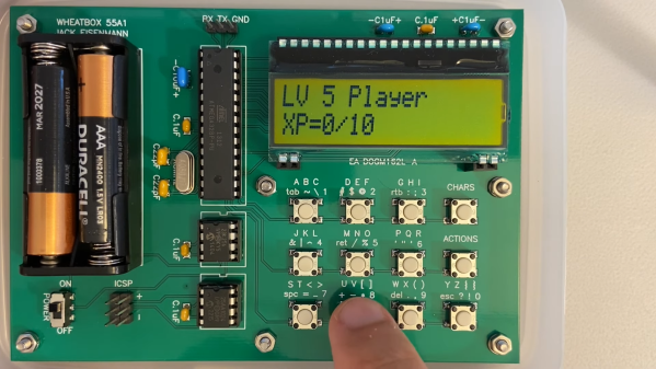
WheatSystem quickly became a basic and functional OS. To demonstrate it, [Esperantanaso] created WheatBox 55A1, a small homebrew computer based on the ATmega328. It readily runs simple applications like a prime number generator or a basic RPG.
Creating one’s own OS is no mean feat, even at the 8-bit level. We’ve seen it done before, and it never fails to impress.