To say that that the commercially available garden path lights commonly available at dollar stores are cheap is a vast overstatement of their true worthlessness. These solar-powered lights are so cheaply built that there’s almost no point in buying them, a fact that led [Mark Presling] down a fabrication rabbit hole that ends with some great tips on powder coating parts with difficult geometries.
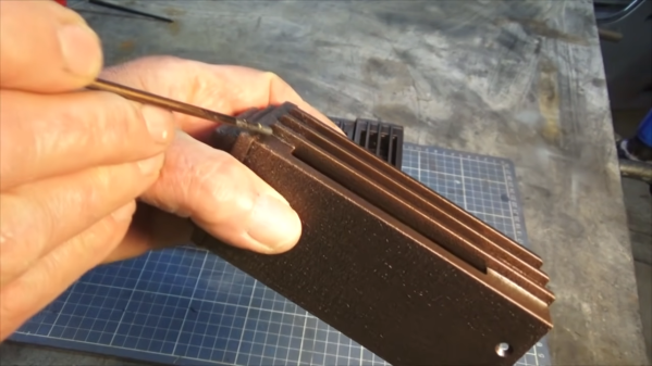
Powder coating might seem a bit overkill for something as mundane as garden lights, but [Mark] has a point — if you buy something and it fails after a few weeks in the sun, you might as well build it right yourself. And a proper finish is a big part of not only getting the right look, but to making these totally un-Tardis-like light fixtures last in the weather. The video series below covers the entire design and build process, which ended up having an aluminum grille with some deep grooves. Such features prove hard to reach with powder coating, where the tiny particles of the coating are attracted to the workpiece thanks to a high potential difference between them. After coating, the part is heated to melt the particles and form a tough, beautiful finish.
But for grooves and other high-aspect-ratio features, the particles tend to avoid collecting in the nooks and crannies, leading to an uneven finish. [Mark]’s solution was to turn to “hot flocking”, where the part is heated before applying uncharged coating to the deep features. This gets the corners and grooves well coated before the rest of the coating is applied in the standard way, leading to a much better finish.
We love [Presser]’s attention to detail on this build, as well as the excellent fabrication tips and tricks sprinkled throughout the series. You might want to check out some of his other builds, like this professional-looking spot welder.
Continue reading “Simple Tip Helps With Powder Coating Perfection On Difficult Parts”