Hinges Live Inside 3D Prints

Since desktop 3D printers have become more common, we’ve seen dramatic shifts in all kinds of areas such as rapid prototyping, antique restoration, mass production of consumer goods, or even household repairs that might not have been possible otherwise. There are a lot of unique manufacturing methods that can be explored in depth with a 3D printer as well, and [Slant 3D] demonstrates how one such method known as the living hinge can be created with this revolutionary new tool.

Living hinges, unlike a metal hinge you might pick up at a hardware store, are integrated into the design of the part and made of the same material. Typically found in plastic containers, they allow for flexibility while keeping parts count and cost low. The major downside is that they create stresses in the materials when used, so their lifespan is finite. But there are a number of ways to extend their life, albeit with a few trade-offs.

The first note is to make sure that you’re using the right kind of plastic, but after that’s taken care of [Slant 3D] builds a few flexible parts starting with longer circular-shaped living hinge which allows greater range of motion and distributes the forces across a wider area, at a cost of greater used space and increased complexity. A few other types of living hinges are shown to use less space in some areas, but make the hinges only suitable for use in other narrower applications.

One of the more interesting living hinges he demonstrates is one that’s more commonly seen in woodworking, known there as a kerf bend. By removing strips of material from a sheet, the entire sheet can be rotated around the cuts. In woodworking this is often done by subtracting material with a CNC machine or a laser cutter, but in 3D printing the voids can simply be designed into the part.

Continue reading “Hinges Live Inside 3D Prints”

Compressed Air Keeps Screws Moving Through Modular Production System

If there’s an unsung hero of manufacturing, it’s the engineer who figures out how to handle huge numbers of small parts. It’s one thing to manually assemble something, picking each nut, bolt, and washer by hand. It’s another thing to build a machine that can do the same thing, but thousands of times in a row, ideally without making mistakes.

Most of us don’t need that level of automation in our processes, but when you do, it results in some interesting challenges. Take this pneumatic screw accelerator that [Christopher Helmke] designed for his modular production system. One of the custom machines in his system is a screw counter, which uses a magnetic wheel to feed screws — or nuts or washers — from a hopper, orient them correctly, and drop them into an output chute. While the counting bit worked quite well, parts would only go so far under the force of gravity in the clear vinyl tube used to connect the counter to the next process.

[Christopher]’s solution was simple but effective. His first prototype simply injects compressed air into the parts feed tube, which pushes the screws through the tubing. It works surprisingly well, propelling the parts through quite a long length of tubing, handling twisting paths easily and even working against gravity. Version 2 integrated the accelerator and a re-orienting fixture into a single part, which mates with a magazine that holds a large number of screws.

There are a lot of interesting features [Christoper] built into these simple parts that are worth keeping in mind. Our favorite is printing channels to guide small cable ties around the tubing to clamp it into the accelerator. We’ll be keeping that trick in mind.

Continue reading “Compressed Air Keeps Screws Moving Through Modular Production System”

FET: The Friendly Efficient Transistor

If you ever work with a circuit that controls a decent amount of current, you will often encounter a FET – a Field-Effect Transistor. Whether you want to control a couple of powerful LEDs, switch a USB device on and off, or drive a motor, somewhere in the picture, there’s usually a FET doing the heavy lifting. You might not be familiar with how a FET works, how to use one and what are the caveats – let’s go through the basics.

Here’s a simple FET circuit that lets you switch power to, say, a USB port, kind of like a valve that interrupts the current flow. This circuit uses a P-FET – to turn the power on, open the FET by bringing the GATE signal down to ground level, and to switch it off, close the FET by bringing the GATE back up, where the resistor holds it by default. If you want to control it from a 3.3 V MCU that can’t handle the high-side voltage on its pins, you can add a NPN transistor section as shown – this inverts the logic, making it into a more intuitive “high=on, low=off”, and, you no longer risk a GPIO!

This circuit is called a high-side switch – it enables you to toggle power to a device at will through a FET. It’s the most popular usecase for a FET, and if you’re wondering more about high-side switches, I highly recommend this brilliant article by our own [Bil Herd], where he shows you high-side switch basics in a simple and clear way. For this article, you can use this schematic as a reference of how FETs are typically used in a circuit.

Continue reading “FET: The Friendly Efficient Transistor”

The BSides: More Curious Uses Of Off-the-shelf Parts

Off-the-shelf stock parts are the blocks from which we build mechanical projects. And while plenty of parts have dedicated uses, I enjoy reusing them in ways that challenge what they were originally meant for while respecting the constraints of their construction. Building off of my piece from last time, I’d like to add to your mechanical hacking palette with four more ways we can re-use some familiar off-the-shelf parts. Continue reading “The BSides: More Curious Uses Of Off-the-shelf Parts”

Ask Hackaday: Split Rail Op Amp Power Supply

Water cooler talk at the office usually centers around movies, sports, or life events. Not at Hackaday. We have the oddest conversations and, this week, we are asking for your help. It is no secret that we have a special badge each year for Supercon. Have you ever wondered where those badges come from? Sometimes we do too. We can’t tell you what the badge is going to be for Supercon 2023, but here’s a chance for you to contribute to its design.

What I can tell you is that at least part of the badge is analog. Part, too, is digital. So we were discussing a seemingly simple question: How do we best generate a bipolar power source for the op amps on a badge? Like all design requests, this one is unreasonable. We want:

  • Ideally, we’d like a circuit to give us +/- 9 V to +/- 12 V at moderately low current, say in the tens of milliamps. Actual values TBD.
  • Low noise: analog circuitry, remember?
  • Lightweight: it is going on a badge
  • Battery operated: the badge thing again
  • Cheap: we only have a couple bucks in the budget for power
  • Available in quantity: we’ll need ~600 of these

Continue reading “Ask Hackaday: Split Rail Op Amp Power Supply”

Homemade Scope Does Supercapacitor Experiments

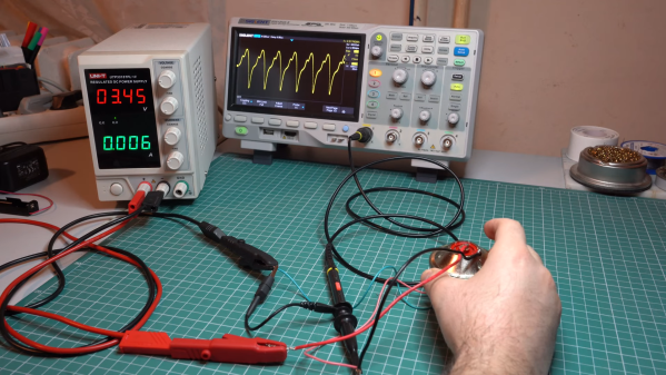
We’ve always been a little sad that supercapacitors aren’t marked with a big red S on a yellow background. Nevertheless, [DiodeGoneWild] picked up some large-value supercapacitors and used his interesting homemade oscilloscope to examine how they worked. You can watch what he is up to in his workshop in the video below.

Supercapacitors use special techniques to achieve very high capacitance values. For example, the first unit in the video is a 500 F capacitor. That’s not a typo — not microfarads or even millifarads — a full 500 Farads. With reasonable resistance, it can take a long time to charge 500F, so it is easier to see the behavior, especially with the homemade scope, which probably won’t pick up very fast signals.

For example, A 350 mA charging current takes about an hour to bring the capacitor up to 2.6 V, just under its maximum rating of 2.7 V. Supercapacitors usually have low voltage tolerance. Their high capacity makes them ideal for low-current backup applications where you might not want a rechargeable battery because of weight, heat, or problems with long-term capacity loss.

The real star of the video, though, is the cast of homemade test equipment, including the oscilloscope, a power supply, and a battery analyzer. To be fair, he also has some store-bought test gear, too, and the results seem to match well.

Supercapacitors are one of those things that you don’t need until you do. If you haven’t had a chance to play with them, check out the video or at least watch it to enjoy the homebrew gear. We usually look to [Andreas Spiess] for ESP32 advice, but he knows about supercaps, too. If you really like making as much as you can, you can make your own supercapacitors.

Continue reading “Homemade Scope Does Supercapacitor Experiments”

Spice Up The Humble 16×2 LCD With Big Digits

The 16×2 LCD display is a classic in the microcontroller world, and for good reason. Add a couple of wires, download a library, mash out a few lines of code, and your project has a user interface. A utilitarian and somewhat boring UI, though, and one that can be hard to read at a distance. So why not spice it up with these large-type custom fonts?

As [upir] explains, the trick to getting large fonts on a display that’s normally limited to two rows of 16 characters each lies in the eight custom characters the display allows to be added to its preprogrammed character set. These can store carefully crafted patterns that can then be assembled to make reasonable facsimiles of the ten numerals. Each custom pattern forms one-quarter of the finished numeral, which spans what would normally be a two-by-two character matrix on the display. Yes, there’s a one-pixel wide blank space running horizontally and vertically through each big character, but it’s not that distracting.

Composing the custom patterns, and making sure they’re usable across multiple characters, is the real hack here, and [upir] put a lot of work into that. He started out in Illustrator, but quickly switched to a spreadsheet because it allowed him to easily generate the correct binary numbers to pass to the display for each pattern. It seems to have really let his creative juices flow, too — he came up with 24 different fonts! Our favorite is the one he calls “Tron,” which looks a bit like the magnetic character recognition font on the bottom of bank checks. Everyone remembers checks, right?

Hats off to [upir] for a creative and fun way to spice up the humble 16×2 display. We’d love to see someone pick this up and try a complete alphanumeric character set, although that might be a tall order with only eight custom characters to work with. Then again, if Bad Apple on a 16×2 is possible…

Continue reading “Spice Up The Humble 16×2 LCD With Big Digits”