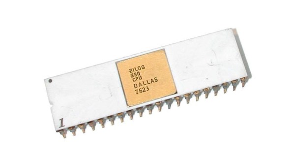
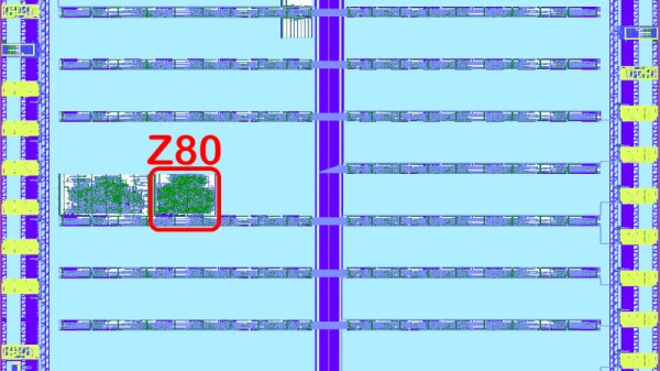
Eliminate That Pesky Power-Only USB Cable With This Cable Tester

Ever wondered why your Arduino wasn’t programming, only to find out that the cable doesn’t have any data conductors? Worry not, [Spencer Maroukis] has got you covered with the USB Sleuth Cable Tester!

The cable tester is a beautiful black circular PCB, with USB ports of nearly every type on the edges. It works partially through passive detection with LEDs and otherwise through active detection of things like the orientation with an STM32 powered by a coin cell battery. But it gets better: There are disconnect switches and exposed pads to test some of the conductors with a digital multimeter!

It may not be necessary for all of us, but one thing is clear: When you needed a good USB cable, you wished you had this to actually test it. The design is open-source too, which is definitely nice if you want one for yourself.

Meanwhile this isn’t the first USB cable tester we’ve seen here.

Ballpoint Switch Is Oh-So Satisfying

Alright, here’s your quick and dirty hack for the day. The astute among you may recall [Peter Waldraff]’s bookshelf train build of a few days ago, and the fact that he used a switch made from a dead ballpoint pen to light up the scene. Fortunately, [Peter] wrote in to give us the details of this low-voltage sub-build, which you can see in the video after the break.

Essentially, [Peter] starts by making a shortened version of the pen. He modifies nearly every bit of it, including cutting down the ink cartridge, so if you try this, make sure the thing is all dried up first. Then, as he is screwing the point holder back on the barrel, he wraps elastic cord around the inside barrel in lieu of having sewing thread lying around. This cord along with some hot glue will hold a pair of paper clips to the sides of the point holder. When the pen is clicked into the writing position, it makes a connection between the paper clips and closes the circuit on whatever is wired into it.

What types of little hacks like this have gotten you through the build? Let us know in the comments, or better yet, write it up and drop us a tip. By the way, here is that bookshelf train build in case you missed it.

Continue reading “Ballpoint Switch Is Oh-So Satisfying”

Lorenz Attractor Analog Computer With Octave Simulation

[Janis Alnis] wanted to build an analog computer circuit and bought some multiplier chips. The first attempt used apparently fake chips that were prone to overheating. He was able to get it to work and also walked through some Octave (a system similar to Matlab) simulations for the circuit. You can follow along in the video below.

Getting the little multiplier chips into the breadboard was a bit of a challenge. Of course, there are a variety of ways to solve that problem. The circuit in question is from the always interesting [Glen’s Stuff] website.

From that site:

The Lorenz system, originally discovered by American mathematician and meteorologist, Edward Norton Lorenz, is a system that exhibits continuous-time chaos and is described by three coupled, ordinary differential equations.

So, the circuit is an analog solution to the system of differential equations. Not bad for a handful of chips and some discrete components on a breadboard. We’ve seen a similar circuit on Hackaday.io.

Check out our recent competition winners if you want to see op amps do their thing. Analog computers were a thing. They aren’t always that complicated, either.

Continue reading “Lorenz Attractor Analog Computer With Octave Simulation”

Inside A Fake LM358

[IMSAI Guy] got some fake LM358 op-amps. Uncharacteristically, these chips actually performed well even though they didn’t act like LM358s. [IMSAI Guy] did a video about the fake chips and someone who saw it offered to analyze the part compared to a real LM358 to see what was going on. You can see it too in the video below.

A visual inspection made it obvious that the chip was probably a fake. X-ray analysis was a little less obvious but still showed poor quality and different internals. But the fun was when they actually decapsulated the part.

Continue reading “Inside A Fake LM358”

Switching Regulators For Dummies

We often use linear regulators in our designs. They are cheap and simple – you put the regulator chip itself on the board, add two capacitors, and get a voltage. Linear regulators are imperfect, of course – they can’t help but waste the voltage difference as heat, for a start, which straight up excludes them for high-current purposes, or significant voltage difference conversions, unless you have a hefty heatsink handy. They also can’t boost voltage, which means you can only go from high to low – a bit of a disappointment.

Of course, we haven’t been just throwing our hands up in the air if a linear regulator doesn’t fit our purpose. Switching regulators have none of these disadvantages, which is why your mobile phone alone has a few dozen of these. They are way more efficient and hi-tec, able to convert one voltage into another while losing hardly any power into heat. All that you need to do is switch an inductor at a somewhat high frequency!

However, for some, switching regulators might look a bit intimidating. They tend to have higher standards for board layout compared to linear regulators, and, they do need an inductor – sometimes, a few more components too. Inductors alone are somewhat intimidating components, with a fair few more parameters than we’d expect, and you might get confused when looking into adding a switching regulator to your circuit.

No more! In this article, I shall give you the switching regulator basics, remove any fog of war that might be clouding your vision, and show you just how easily you can get a good few amps at your favourite voltage whenever you need it. Continue reading “Switching Regulators For Dummies”

Erasing EEPROMs Isn’t Always As Easy As It Seems

When is 14 volts not actually 14 volts? Given [Anders Nielsen]’s recent struggles with erasing an old-school EEPROM, it’s when you really need it that things tend to go pear-shaped.

A little background is perhaps in order. [Anders] is working on a scratch-built programmer for ROMs to complement his 65uino project, which puts a complete 6502 computer into the footprint of an Arduino Uno. He wisely started the ROM programmer project at the beginning, which was to generate the correct voltages for programming. This turned out to be not as easy as you might think thanks to the solderless breadboard’s parasitic effects on the MIC2288 switching boost regulator he chose.

The video below is a continuation of the programmer build, which ends up being just as fraught as the first part. Being able to generate the programming voltages is one thing; getting them onto the right pins at the right time using nothing but the 5-volt GPIOs on a microcontroller is another. In true retro fashion, [Anders] tackled that problem with a pair of small-signal transistors, which seemed to work once the resistor values were sorted, at least when applying a 12-volt signal intended to show the ROM’s hard-coded manufacturer ID on the data bus.

But erasing the ROM, which requires 14 volts while the chip enable line is held high for 100 ms, proved a little trickier. Despite multiple tries, the ROM wouldn’t erase thanks to the 14-volt rail being dragged down to around 9 volts. [Anders] fixed that with a new base resistor on the driver, to increase the current and keep the voltage up where it needs to be. Just goes to show you that the data sheets don’t always tell the whole story.

We’ve been enjoying the unfolding story of this programmer, and we’re looking forward to the next installment.

Continue reading “Erasing EEPROMs Isn’t Always As Easy As It Seems”

Displays We Love Hacking: SPI And I2C

I’ve talked about HD44780 displays before – they’ve been a mainstay of microcontroller projects for literal decades. In the modern hobbyist world, there’s an elephant in the room – the sheer variety of I2C and SPI displays you can buy. They’re all so different, some are LCD and some are OLED, some have a touchscreen layer and some don’t, some come on breakouts and some are a bare panel. No matter which one you pick, there are things you deserve to know.

These displays are exceptionally microcontroller-friendly, they require hardly any GPIOs, or none extra if you already use I2C. They’re also unbelievably cheap, and so tiny that you can comfortably add one even if you’re hurting for space. Sure, they require more RAM and a more sophisticated software library than HD44780, but with modern microcontrollers, this is no problem at all. As a result, you will see them in almost every project under the sun.

What do you need for those? What are the requirements to operate one? What kind of tricks can you use with them? Let’s go through the main aspects.

Continue reading “Displays We Love Hacking: SPI And I2C”