Wildlife Camera

Remote Controlled Wildlife Camera With Raspberry Pi

If you are interested in local wildlife, you may want to consider this wildlife camera project (Google cache). [Arnis] has been using his to film foxes and mice. The core components of this build are a Raspberry Pi and an infrared camera module specifically made for the Pi. The system runs on a 20,000 mAh battery, which [Arnis] claims results in around 18 hours of battery life.

[Arnis] appears to be using a passive infrared (PIR) sensor to detect motion. These sensors work by detecting sudden changes in the amount of ambient infrared radiation. Mammals are good sources of infrared radiation, so the sensor would work well to detect animals in the vicinity. The Pi is also hooked up to a secondary circuit consisting of a relay, a battery, and an infrared light. When it’s dark outside, [Arnis] can enable “night mode” which will turn on the infrared light. This provides some level of night vision for recording the furry critters in low light conditions.

[Arnis] is also using a Bluetooth dongle with the Pi in order to communicate with an Android phone. Using a custom Android app, he is able to connect back to the Pi and start the camera recording script. He can also use the app to sync the time on the Pi or download an updated image from the camera to ensure it is pointed in the right direction. Be sure to check out the demo video below.

If you like these wildlife cameras, you might want to check out some older projects that serve a similar purpose. Continue reading “Remote Controlled Wildlife Camera With Raspberry Pi”

More Power For Raspberry Pi USB Ports

Since the Raspberry Pi 2 was released, everyone building RetroPi emulators has been graced with four USB ports. For those of us doing useful stuff with the Pi, those ports are a little anemic: you can’t plug in a webcam and a WiFi module at the same time without suffering CPU brownouts. The maximum current all USB peripherals can draw from the USB port is 600mA. By changing a value in the /boot/config.txt file, this current limit can be increased to 1.2A for all four ports.

Pisquare
The yellow line traces the signal from the GPIO to the USB power switch.

Because the USB current limit is set in software, there must be a few bits of hardware that do the actual work. Tucked away below the right hand of the GPIO header is the hardware that does exactly that. It’s an AP2253 current-limited power switch (PDF), and the current is adjustable by tying a resistor to pin 5 on the chip.

Pin 5 on the AP2253 is connected to two resistors. One resistor goes directly to a ground plane, while the other is switched through a FET. The gate of this FET goes to another resistor, and when a GPIO pin is high, these resistors are wired in parallel. This means the resistance is halved when the GPIO pin is high, doubling the current limiting circuit in the AP2253.

This setup provides a relatively easy mod to increase the current limiting of the USB ports so they can provide 4x500mA, meeting the USB spec. The AP2253 power switch’s current limiting can be set by a single resistor, anywhere from 10kΩ to 232kΩ. By removing R50 and R4, and replacing R50 with a 10kΩ resistor, the current limiting of the AP2253 switch will be set to its maximum, 2.1A. Divide that by four, and you have 500mA per port, just like every other computer on the planet.

There is a reason the Raspberry Pi foundation set the current limiting of the USB ports so low. The Pi was originally intended to run off of a micro USB phone charger. There aren’t many phone chargers out there that will supply more than 1A, and the CPU and related peripherals will take half of that. If you’re going to change the /boot/config.txt file, you’re going to need a beefy power supply. Increasing the current limiting of the USB ports to 2A will require an even bigger, beefier supply.

The 2G Raspberry Pi Smartphone

For [Tyler]’s entry to the Hackaday Prize, he’s making something that just a few years ago would be unheard of in a homebrew build. He’s making a DIY smartphone. Yes, with cheap single-board Linux computers, GSM modules, and SPI touchscreen displays, it’s possible to build your own smartphone.

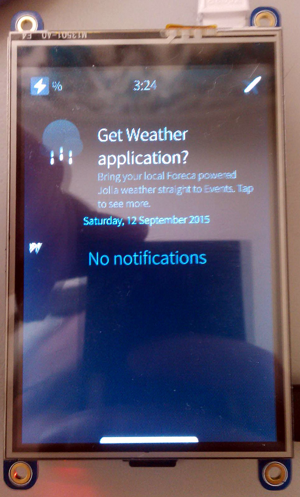
Inside [Tyler]’s DIY smartphone is a Raspberry Pi Model A, a 3.5 inch touchscreen PiTFT with 480×320 resolution, and an Adafruit FONA module The connections are simple enough; the TFT is connected over SPI, and the GSM module over serial. The entire device is powered by a 1200mAh LiIon battery, charged with a powerboost board, runs an operating system written in Python capable of making calls, sending texts, and takes pictures with a Pi camera.

This is not what you would normally call a smartphone. The FONA module is 2G only, meaning you’re limited to 2G speeds and 2G networks. AT&T will be shutting down 2G networks in a little bit, although T-Mobile will be keeping them up for anyone who still has an old Nokia Brick.

That said, [Tyler]’s phone is still exactly what you want in a minimal phone: it just makes calls and receives texts, it has a camera, and unlike the Nokia, you can take it apart and repair it easily. Not that you ever had to do that with a Nokia…

The Raspberry Pi Wearable Revolution

With the human URL [will.i.am] serving as Chief Creative Director of 3D Systems, and [Martha Stewart] selling her own line of 3D printer filament through MakerBot, more and more celebrities are piling onto the hacker, maker, and DIY revolution. Now, the partnership we’ve all been waiting for: the Raspberry Pi Foundation and [The Artist Formerly Known As Prince_logo] are teaming up to produce a line of Pi-based wearable electronics. The first product from this new, fashionable line of electronics is beyond anything you would expect. It’s called the Raspberry Beret, and it’s shaping up to be a Revolution in wearables.

The wearable Raspberry Beret is exactly what you would expect: a habadasher’s masterpiece that pairs equally well with figure skating costumes and skin-tight cloud print suits. Inside, though, is a new piece of hardware based on the Raspberry Pi compute module. This module includes a Bluetooth module that will sync with any Windows phone. The Raspberry Beret also includes enough sensors that will blow away everything from a Fitbit to the new Apple Watch. The Raspberet will keep track of your heart rate, activity, and exercise routine.

The Raspberry Beret is just the beginning; the Pi Foundation and [The Artist Formerly Known As Prince_logo] are also teaming up with OSH Park to produce a limited, special edition Raspberry Pi 2. This board will be clad in the beautiful OSH Park purple soldermask and sports 4GB of eMMC Flash. This Flash will not be usable; instead it will contain a remastered edition of Purple Rain that will play as a startup chime. There will be no option to skip the chime.

Pancakes.

Transmitting HD Video From A Raspberry Pi

It’s been a few years since the RTL-SDR TV Tuner dongle blew up the world of amateur radio; it’s a simple device that listens in on digital television frequencies, but it’s one of those tools that’s just capable enough to have a lot of fun. Now, we have a transmitting dongle. It’s only being used to transmit live HDTV from a Pi, but that in itself is very interesting and opens up a lot of possible builds.

The key piece of hardware for this build is a UT-100C DVB-T modulator. It’s a $169 USB dongle capable of transmitting between 1200-1350 MHz, and with a special edition of OpenCaster it’s possible to transmit over-the-air TV. There’s no amplifier, so you won’t be sending TV very far, but it does work.

On the Raspberry Pi side of the build, the standard camera captures H.264 video with raspivid, which is converted to a DVB compliant stream using ffmpeg. These are well-worn bits of software in the Raspberry Pi world, and OpenCaster takes care of the rest.

While this seems like the perfect solution to completely overbuilt quadcopters, keep in mind transmitting on the 23cm band does require a license. Transmitting in the UHF TV bands is a bad idea.

The Pi 2 Means Faster GPIO

The Raspberry Pi is a great machine to learn the ins and outs of blinking pins, but for doing anything that requires blinking pins fast, you’re better off going with a BeagleBone. This has been the conventional wisdom for years now, and now that the updated Raspberry Pi 2 is out, there’s the expectation that you’ll be able to blink a pin faster. The data are here, and yes, you can.

The method of testing was connecting a PicoScope 5444B to a pin on the GPIO pin and toggling between zero and one as fast as possible. The original test wasn’t very encouraging; Python maxed out at around 70 kHz, Ruby was terrible, and only C with the native library was useful for interesting stuff – 22MHz.

Using the same experimental setup, the Raspberry Pi 2 is about 2 to three times faster. The fastest is still the C native library, topping out at just under 42 MHz. Other languages and libraries are much slower, but the RPi.GPIO Python library stukk sees a 2.5x increase.

Hackaday Retro Edition: Remaking The PDP 8/I With A Raspberry Pi

[Oscar] really likes the PDP-8s, with the extremely old school PDP-8/I being his favorite. If you haven’t checked the price on these recently, getting a real PDP-8/I is nigh impossible. However, after assembling a KIM-1 clone kit, an idea struck: what about building a modern PDP-8/I replica that looks like the real thing, but is powered by modern hardware. This would be fairly cheap to build, and has the added bonus of not weighing several hundred pounds.

The PiDP-8 is [Oscar]’s project to replicate the hardware of the 8/I in a modern format. Instead of hundreds of Flip Chips, this PDP-8 is powered by a Raspberry Pi running the SIMH emulator. The 40-pin GPIO connector on the Pi is broken out to 92 LEDs and 26 toggle switches on a large PCB. This setup gets [Oscar] a reasonable facsimile of the PDP-8/I, but he’s also going for looks too. He created an acrylic panel with artwork copied from an original 8/I  that mounts to the PCB and gives the entire project that beautiful late 60s / early 70s brown with harvest gold accent color scheme.

Since this emulated PDP-8/I is running on entirely new hardware, it doesn’t make much sense to haul out disk drives as big as a small child, tape drives, and paper tape readers. Instead, [Oscar] is putting everything on USB sticks. It’s a great solution to the problem of moving around files that are a few kilowords in size.

vt100normal[Oscar] says he’ll be bringing his PiDP to the Vintage Computer Festival East X in Wall, NJ, April 17-19. We’ll be there, and I’ve already offered [Oscar] the use of a VT-100 terminal. If you’re in the area, you should come to this event. It’s guaranteed to be an awesome event and you’re sure to have a great time. Since this is the 50th anniversary of the introduction of the PDP-8, there will be a half-dozen original PDP-8s set up, including a newly refurbished Straight-8 that came out of the RESISTORS.

Oh, if anyone knows how to connect a Pi to a VT100 (technically a 103), leave a note in the comments. Does it need the RTS/CTS?