[CuriousMarc] Repairs A Floppy

[CuriousMarc] has a pile of 8-inch drives, all marked bad. You can’t just pop over to the computer store and buy a new one these days, so it was off to the repair bench. Although the target drive would do a quick seek,  once it was in use, it just kind of shut down. So [Marc] started sending low-level commands to the device to see if he could isolate the fault. You can watch the whole adventure in the video below.

Using a breakout board, he was able to monitor and exercise all the pins going into the floppy. A quick study of the schematics, and connection to the scope were all [Marc] needed to build some theories of what was happening.

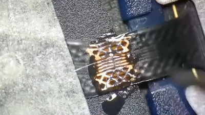
One of the theories was that the head amplifier was disabled, but it turned out to be fine. After several other dead ends, he finally found a broken spring and came up with a creative repair for it. But there was still no clear reason why the drive wouldn’t work. By process of elimination, he started to suspect an array of diodes used for switching, but again, it was another dead end.

Luckily, he had one working drive, so he could compare things between them. He found a strange voltage difference. Turns out the old advice of checking power first might have paid off here. One of the voltage regulator ICs was dead. In all fairness, there are two 12V power supplies and he had checked one of them but had missed the second supply.  This supply is only used for head bias which switches the diodes he had suspected earlier. There had also been a loose pin that might have been a contributor.

With a new power supply IC, the drive worked but needed an alignment. You may never need to repair an 8-inch floppy drive, but the logic in chasing down a problem like this will serve you well on any diagnostic task.

If you think the big drives won’t work with a modern PC, they will. On the other hand, if you need to read some badly enough, you could just use an oscilloscope.

Continue reading “[CuriousMarc] Repairs A Floppy”

Reviving A Legend: Mamiya RB67 Repair

The damaged parts in the camera are circled in red. Original graphic is from the Mamiya service manual.

When it comes to professional medium format analog cameras, the Mamiya RB67 is among the most well-known and loved, ever since its introduction in 1970. Featuring not only support for 120 and 220 film options, but also a folding and ‘chimney’ style view finder and a highly modular body, these are just some reasons that have made it into a popular – if costly – reflex system camera even today. This is one reason why [Anthony Kouttron] chose to purchase and attempt to repair a broken camera, in the hopes of not only saving a lot of money, but also to save one of those amazing cameras from the scrap heap. Continue reading “Reviving A Legend: Mamiya RB67 Repair”

Europe’s Proposed Right-To-Repair Law: A Game Changer, Or Business As Usual?

Recently, the European Commission (EC) adopted a new proposal intended to enable and promote the repair of a range of consumer goods, including household devices like vacuum cleaners and washing machines, as well as electronic devices such as smartphones and televisions. Depending on how the European Parliament and Council vote in the next steps, this proposal may shape many details of how devices we regularly interact with work, and how they can be repaired when they no longer do.

As we have seen recently with the Digital Fair Repair Act in New York, which was signed into law last year, the devil is as always in the details. In the case of the New York bill, the original intent of enabling low-level repairs on defective devices got hamstrung by added exceptions and loopholes that essentially meant that entire industries and types of repairs were excluded. Another example of ‘right to repair’ being essentially gamed involves Apple’s much-maligned ‘self repair’ program, that is both limited and expensive.

So what are the chances that the EU will succeed where the US has not?

Continue reading “Europe’s Proposed Right-To-Repair Law: A Game Changer, Or Business As Usual?”

A picture of the bottom of the Pi 4 PCB, showing the three points you need to use to tap into the Pi 4 I2C bus going to the PMIC

Dead Raspberry Pi Boards, PMICs, And New Hope

Since the Raspberry Pi 3B+ release, the Pi boards we all know and love gained one more weakpoint – the PMIC chip, responsible for generating all the power rails a Pi needs. Specifically, the new PMIC was way more vulnerable to shorting 5V and 3.3V power rails together – something that’s trivial to do on a Raspberry Pi, and would leave you with a bricked board. Just replacing the PMIC chip, the MxL7704, wouldn’t help since the Raspberry Pi version of this chip is customized – but now, on Raspberry Pi forums, [Nefarious19] has reportedly managed to replace it and revive their Pi.

First off, you get a replacement PMIC and reflow it – and that’s where, to our knowledge, people have stopped so far. The next step proposed by [Nefarious19] is writing proper values into the I2C registers of the PMIC. For that, you’d want a currently-alive Pi – useful as both I2C controller for writing the values in, and as a source of known-good values. That said, if you go with the values that have been posted online, just having something like a Pi Pico for the I2C part ought to be enough.

[Nefarious19] reports a revived Pi, and this is way more hopeful than the “PMIC failures are unfixable” conclusion we’ve reached before. The instructions are not quite clear – someone else in the thread reports an unsuccessful attempt doing the same, and it might be that there’s a crucial step missing in making the values persist. However, such an advancement is notable, and we trust our readers to take the lead.

A week ago, [Mangy_Dog] on Hackaday Discord brought up fixing Raspberry Pi boards – given that the Raspberry Pi shortages are still an issue, digging up your broken Pi and repairing it starts making sense budget-wise. It’s no longer the ages where you could buy broken Pi boards by the hundred, and we imagine our readers have been getting creative. What are your experiences with fixing Raspberry Pi boards?

Fresh PCBs For The Quickshot II And II Plus Joysticks

The Quickshot II was released by Spectravideo in 1983 for the Commodore 64 and compatible systems, with the Quickshot II Plus following the next year. After decades of regular use, it’s quite understandable that these old-timers may be having some functional issues, but as long as the plastic parts are still good, [Stephan Eckweiler]’s replacement PCBs may be just the thing that these joysticks need to revitalize them for another few decades.

What may be a matter of taste is that these replace the nice tactile clicky switches on the QS II Plus with SMD push buttons, but compared to the stamped metal ‘button’ construction of the original QS II, the new board is probably a major improvement. As for the BOM, it features two ICs: a 74LS00 latch and NE555 timer, along with the expected stack of passives and switches, both through-hole and SMD.

The PCB contains break-off boards for the switches within the joystick itself, requiring a bit of wiring to be run to the main PCB before soldering on the DE-9 connector and connecting the joystick for a test run to a Commodore 64. All one needs now is a 3D printable enclosure version to create more QS II joysticks for some multiplayer action.

Replacing A Clock IC’s Battery

You can find a lot of strange things inside IC packages. For example, the Dallas DS12885 and DS12887 real time clock “chips” were available in a large package with an internal battery. The problem, of course, is that batteries die. [New Old Computer Show] wanted to restore a machine that used one of these devices and was able to repair the device. You can see two videos below. In the first video, he replaces both the battery and adds an external oscillator which would be necessary for the DS12885. However, he actually had the DS12887, which has an internal oscillator, something the second video explains.

The repair used a PCB he ordered from Tindie. However, the board is only part of the problem. You also need to disconnect the dead battery which requires a Dremel and a steady hand.

Continue reading “Replacing A Clock IC’s Battery”

Pi Picos Give Casio FX9000P Its Memory Back

Is the Casio FX9000P a calculator or a computer? It’s hard to tell since Casio did make calculators that would run BASIC. [Menadue] didn’t know either, but since it had a CRT, a Z80, and memory modules, we think computer is a better moniker.

He found one of these, but as you might expect, it needed a bit of work. There were two bad video RAM chips on the device, and [Menadue] used two Raspberry Pi Picos running a program to make them think they are RAM chips. The number of wires connecting the microcontollers might raise some eyebrows, but it does appear to get the job done.

He also used more Picos to emulate memory on cartridges. Then he used a test clip and a — you guessed it — another Pico to monitor the Z80 bus signals. It is amazing that the Pico can replace what would have been state-of-the-art memory chips and a very expensive logic analyzer.

The second video mostly shows the computer in operation. The use of Picos to stand in for so much is clever. It reminded us of the minimal Z80 computer that used an Arduino for support chips. The computer itself, though, reminded us more of a cheap version of the HP9845.

Continue reading “Pi Picos Give Casio FX9000P Its Memory Back”