Some design choices on manufacturing equipment really leave you scratching your head for a while, as recently happened to [Chris Cecil] when the belt on a reflow oven’s conveyer snapped. Although the solution seems simple enough, getting a new belt on the thing would involve essentially taking the entire machine apart, before reassembling it again. Thus the frayed belt went through the oven over and over until during a recent production run of Smoothieboard controller boards until [Chris] heard a funny noise and the conveyer ground to a halt.
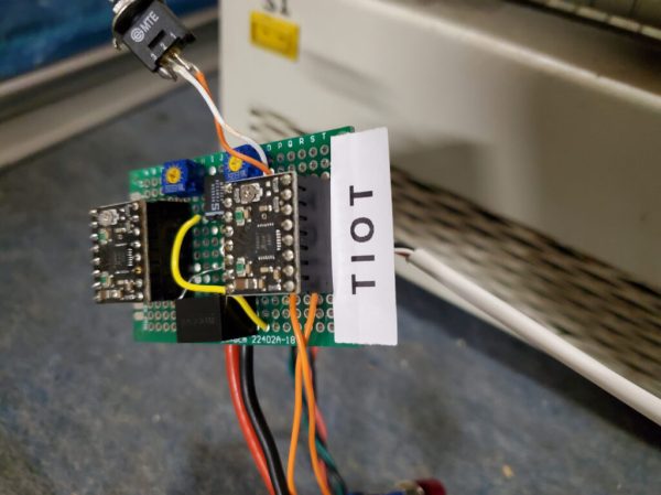
Moving the conveyer by hand kind of worked, but with a more permanent fix urgently needed to finish the production run, two stepper motors took the place of the belt, which just left driving these steppers to keep the conveyer moving in sync. Lacking a simple Arduino board to toss at it, and with a Smoothieboard being absolute overkill, [Chris] figured that a humble NE555 timer IC ought to do the job just as well.
Using a project on Hackaday.io by [KushagraK7] as the starting point, and a 1992-vintage NE555 IC harvested from an old project, [Chris] managed to put together a basic stepper driver that uses the NE555 to provide the timing signal. In addition to restoring basic functionality like starting and stopping the conveyer belt, [Chris] added a new feature with the reversing of the conveyer direction. Along with some cobbled together components to physically rotate the conveyer’s two rollers, it restored the reflow oven to working condition.
And one day the prototyped driver board will be updated to a proper PCB. It’s only temporary, after all :)
Continue reading “Fixing A Reflow Oven’s Conveyer Belt With An NE555 And Stepper Motors”