The junk bin can be a great source of inspiration, unless you’re too familiar with the contents to be imaginative with them. But thrift stores are another matter, like giant junk bins that are constantly replenished by underappreciated elves. You never know what kinds of goodies they will pile on the shelves, so it’s easy to become a fixture and visit them once or thrice a week.
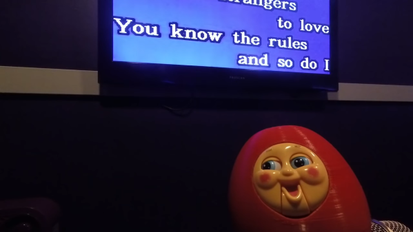
[Hunter Irving] haunts a few choice thrift stores in his neighborhood, and a few months ago he found a knockoff Thomas the Tank Engine with an articulated face. It uses a simple mechanism to produce an impressive amount of movement, especially for a cheap knockoff toy. Both of its eyes slide sideways and its mouth opens, resulting in a very animated (and terrifying) range of expressions. Sensing an opportunity to turn his animatronic robot dreams into karaoke-singing nightmare fuel for the rest of us, he forked over a few bucks and took it home.
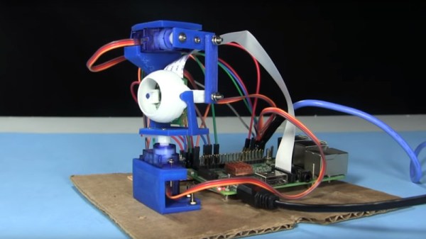
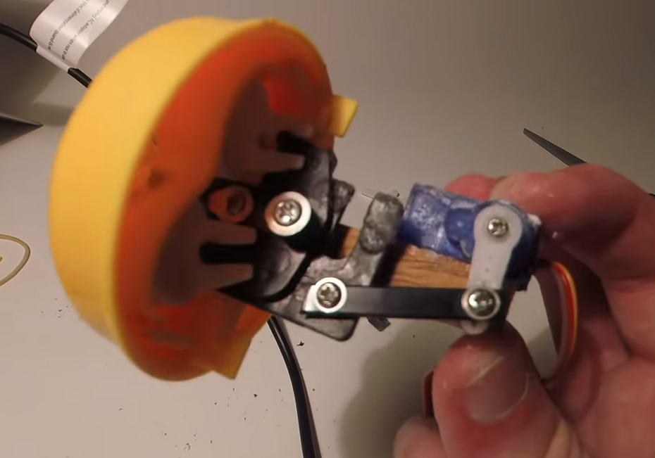 As luck would have it, a 9g micro servo fit perfectly in the back of the frightening little face. [Hunter] designed an axle to transfer motion to the face mechanism, but it broke almost immediately. We applaud his Plan B, though, which consists of a mounting block for the servo, and a cable tie armature connected with screws. Once that was sorted, [Hunter] designed a bulbous body for it in Blender.
This terrifying train-faced toy uses an Arduino Leonardo to read MIDI note-on and -off messages, and opens his mouth when appropriate to sing hit favorites in a smooth, speech-synthesized contralto. Pour yourself a strong beverage and enjoy the build/demo video after the break.
Interested in making your own? [Hunter] has all the files up on his Patreon page. For just $1, you can access the code, synth files, and STL files. While you’re there, you can also get the scoop on his Nintendo LABO waveform cards.
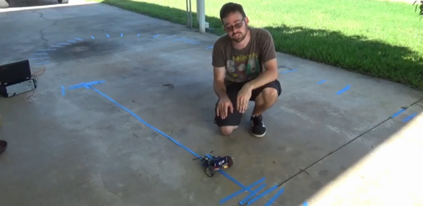
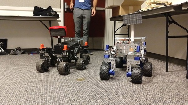


 The aim of the project was to demonstrate the feasibility of a rover exploring a planetary surface, picking up, and examining rocks. Lest you imagine a billion dollar budget for gleaming rover prototypes, it’s fair to say that this was to be achieved with considerably more modest means. The rover was a repurposed unit that had previously been used for remote handling of hazardous chemicals, and the project’s computer was an extremely obsolete DEC PDP-1.


