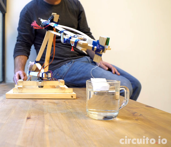
A robot assistant would make the lives of many much easier. Luckily, it’s possible to make one of your own with few fancy materials. The [circuito.io] team demonstrates this by building a robot arm out of recyclables!
With the exception of the electronics — an Arduino, a trio of servo motors, and a joystick — the arm is made almost completely out of salvaged recyclables: scrap wood, a plastic bottle, bits of plastic string and a spring. Oh, and — demonstrating yet another use for those multi-talented tubers — a potato acts as a counterweight.
Instead of using screws or glue, these hackers used string made from a plastic bottle as a form of heat shrink wrap to bind the parts of the arm together. The gripper has only one pivoting claw for greater strength, and the spring snaps it open once released. Behold: your tea-bag dunking assistant.
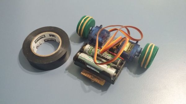
Line Followers are a tried-and-true type of robot; both hardware and software need to be doing their job in harmony in order to be successful at a clearly defined physical task. But robots don’t always have microcontrollers and software, as [Mati_DIY]’s zero programming analog line follower demonstrates.
For readers used to seeing a Raspberry Pi or Arduino in almost everything, an analog robot whose “programming” exists only as a harmony between its discrete parts can be an eye-opener as well as an accessible project. A video of the robot in action is embedded below.
[Mati_DIY]’s design uses two CNY70 reflective sensors (which are essentially infrared emitter/phototransistor pairs) and an LM358 dual op-amp. Together, the sensors act as two near-sighted eyes. By using the output of each sensor to drive a motor via a transistor, the presence or absence of the black line is directly and immediately reflected by the motion of the attached motor. The more black the sensor sees, the more the motor turns. Electrically, that’s all that happens; but by attaching the right sensor to the left motor and the left sensor to the right motor, you get a robot that always tries to keep the black line centered under the sensors. Playing with the spacing of the motors and sensors further tweaks the performance.
[FESTO] keeps coming up with new tricks that make us both envious and inspired. Take their bionicANTs for example. Watching a group of them cooperate to move objects around looks so real that you’re instantly reminded of the pests crawling across your floor, but looking at them up close they’re a treasure trove of ideas for your next robot project.
Ant exoskeleton as circuit board
The exoskeleton is 3D printed but they then use the outer surface of that exoskeleton as a circuit board for much of the circuitry. The wiring is “painted on” using a 3D MID (Molded Interconnect Device) process. While FESTO didn’t give specifics about their process, a little research shows that 3D MID involves the 3D printed object being made of a special non-conductive metal material, a laser then “drawing” the traces in the material, and then dipping the object in various baths to apply copper, nickel and gold layers. We mortal hackers may not have the equipment for doing this ourselves in our workshops but seeing the beautiful result should be inspiration enough to get creative with our copper tape on the outer surfaces of our 3D printed, CNC’d, or hand-carved parts.
We also like how they took a the mouse sensor from under a regular computer mouse and attached it to the ant’s underside, pointing down for precision dead reckoning. For the legs they used three piezo bending transducers. However, these give a deflection of only 1.5mm in both directions, not enough for walking. They increase this to over 10mm with the addition of a plastic hinge, another idea to keep in mind when building that next tiny robot. And there are more ideas to be taken advantage of in their ants, which you can see being built in the video below.
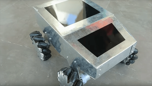
Some scrap wood, a few pieces of sheet metal, a quartet of old gear motors, and a few basic hand tools. That’s all it takes to build an omni-bot with Mecanum wheels, if you’ve got a little know-how too.
For the uninitiated, Mecanum wheels can rotate in any direction thanks to a series of tapered rollers around the circumference that are canted 45° relative to the main axle. [Navin Khambhala]’s approach to Mecanum wheel construction is decidedly low tech and very labor intensive, but results in working wheels and a pretty agile bot. The supports for the rollers are cut from sheet steel and bent manually to hold the wooden rollers, each cut with a hole saw and tapered to a barrel shape on a makeshift lathe. Each wheel is connected directly to a gear motor shaft, and everything is mounted to a sheet steel chassis. The controls are as rudimentary as the construction methods, but the video below shows what a Mecanum-wheeled bot can do.
There’s a lot of room here for improvement, but mainly in the manufacturing methods. The entire wheel could be 3D printed, for instance, or even laser cut from MDF with a few design changes. But [Navin] scores a win for making a working wheel and a working bot from almost nothing.
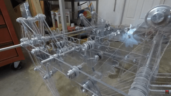
This Strandbeest is ready for the security line at a security-conscious high school. Like see-though backpacks, its clear polycarbonate parts let you see everything that goes into the quirky locomotion mechanism. Despite having multiple legs, if you analyze the movement of a Strandbeest it actually moves like a wheel.
For us, it’s the narrated fabrication video found below that makes this build really interesting. Hackaday alum [Jeremy Cook] has been building different versions of [Theo Jansen’s] Strandbeest for years now. Strandmaus was a small walker controlled by a tiny quadcopter, and MountainBeest was a huge (and heavy) undertaking. Both were made out of wood. This time around [Jeremy] ordered his polycarbonate parts already cut to match his design. But it’s hardly a walk on the beach to make his way to final assembly.
The holes to accept the hardware weren’t quite large enough and he had to ream them out to bring everything together. We enjoyed seeing him build a jig to hold the spacers for reaming. And his tip on using an offset roll pin to secure the drive gear to the motor shaft is something we’ll keep in mind.
In the end, things don’t go well. He had machined out a motor coupling and it ends up being too weak for the torque driving the legs. Having grown up watching [Norm Abram] build furniture (and houses) without a single blown cut or torn-out end grain this is a nice dose of reality. It’s not how perfect you can be with each step, it’s how able you are to foresee problems and correct them when encountered.
I never had the musical talent in me. Every now and then I would try to pick up a guitar or try and learn the piano, romanticising a glamorous career out of it at some point. Arpeggio – the Piano SuperDroid (YouTube, embedded below) sure makes me glad I chose a different career path. This remarkable machine is the brain child of [Nick Morris], who spent two years building it.
Although there are no detailed technical descriptions yet, at its heart this handsome robot consists of a set of machined ‘fingers’ connected to a set of actuators — most likely solenoids . The solenoids are controlled by proprietary software that combines traditional musical data with additional parameters to accurately mimic performances by your favourite pianists, right in your living room. Professional pianists, who were otherwise assuming excellent job security under Skynet, clearly have to reconsider now.
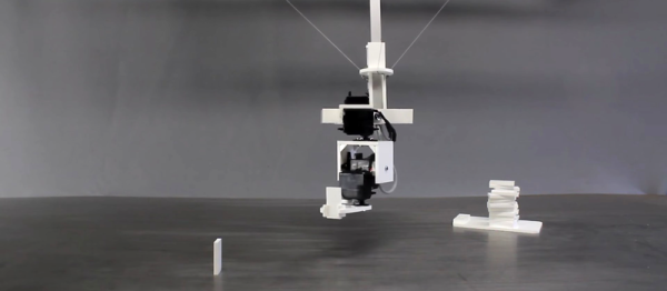
The trademark hacker style of Hessian YouTuber [Homo Faciens] is doing a lot with a little. Given a package of parts from a sponsor, he could have made something “normal” like a fancy robot arm. Instead, he decided to make a winchbot. (Video embedded below.)
What’s a winchbot? It’s a big frame that supports three relatively heavy motors that pull steerable gripping arms around. It’s a little bit like the hanging Hektor / wallbot / plotterbot and a little bit like a delta-style 3D printer. Although [Homo Faciens]’s build doesn’t showcase it, a winchbot is also a great way to lift heavy things because the parts that need to be beefy — the frame and the lifting motors — don’t have to move. We love the gimballed square rod that works in concert with the winches!
With five extra servos on hand, and the computing power of a Raspberry Pi, [Homo Faciens] couldn’t just stop with lifting a claw. Instead, the gripping-arms part of the bot is mounted with four degrees of freedom and is powered with software that makes it stay parallel with the table and rotate around the gripper to make programming easier. Watch it in action in the video to see what we mean.
The biggest unsolved problem that we can see is the jerkiness that it displays in moving things around. That doesn’t stop it from building up a tower and a domino knock-down. We suspect that there’s some combination of firmware and hardware tweaking that can solve this problem, or it could just be run slowly so that the wobbles damp themselves out. We’re also quite confident that [Homo Faciens] will come up with an elegant and cheap solution. Have you seen his CNC machine?

 Instead of using screws or glue, these hackers used string made from a plastic bottle as a form of heat shrink wrap to bind the parts of the arm together. The gripper has only one pivoting claw for greater strength, and the spring snaps it open once released. Behold: your tea-bag dunking assistant.